Product Description
Product Description
|
Technology |
Powder Metallurgy |
Metal injection moding |
|
General Material |
Fc5718/Fn5718 |
17-4Ph/4605 |
|
Density |
6.7-6.8 |
7.7-7.8 |
|
Hardness |
Fc5718(20-30HRC) Fn5718(35-40HRC) |
17-4Ph(35-40HRC) 4605(45-50HRC) |
|
Application |
Medical apparatus and instruments Hardware field Automobile industry Home appliances |
|
Main Advantages
1) Powder metallurgy can ensure the accuracy and uniformity of the material composition ratio.
2) Suitable for producing products of the same shape and large quantities, low production cost.
3) The production process is not afraid of oxidation, and no material pollution will occur.
4) No subsequent machining processing is required, saving materials and reducing costs.
5) Most difficult metals and compounds, pseudo alloys, porous materials can only be manufactured by powder metallurgy
FAQ
Q: Are you trading company or manufacturer ?
A: We are factory and trading company
Q: How long is your delivery time?
A: Generally it is 5-10 days if the goods are in stock. or it is 15-20 days if the goods are not in stock, it is according to quantity.
Q: Do you provide samples ? is it free or extra ?
A: Yes, we could offer the sample for free charge but do not pay the cost of freight.
Q: What is your terms of payment ?
A: Payment=1000USD, 30% T/T in advance ,balance before shippment.
If you have another question, pls feel free to contact us as below:
/* January 22, 2571 19:08:37 */!function(){function s(e,r){var a,o={};try{e&&e.split(“,”).forEach(function(e,t){e&&(a=e.match(/(.*?):(.*)$/))&&1
| Application: | Machinery, Agricultural Machinery |
|---|---|
| Hardness: | Soft Tooth Surface |
| Gear Position: | External Gear |
| Manufacturing Method: | Cast Gear |
| Toothed Portion Shape: | Spur Gear |
| Material: | Cast Steel |
| Customization: |
Available
| Customized Request |
|---|
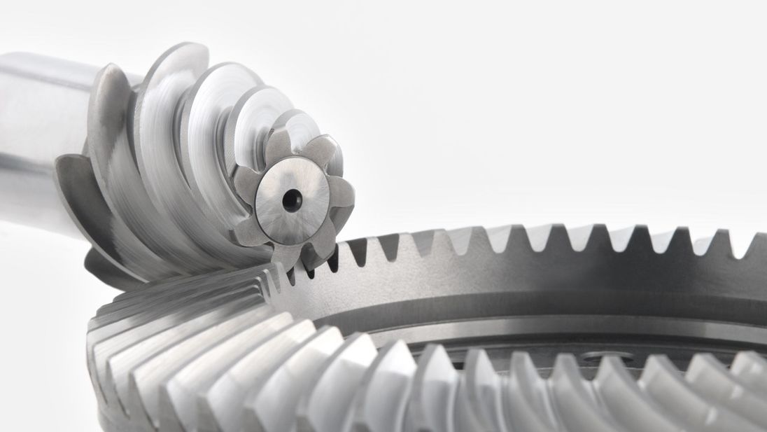
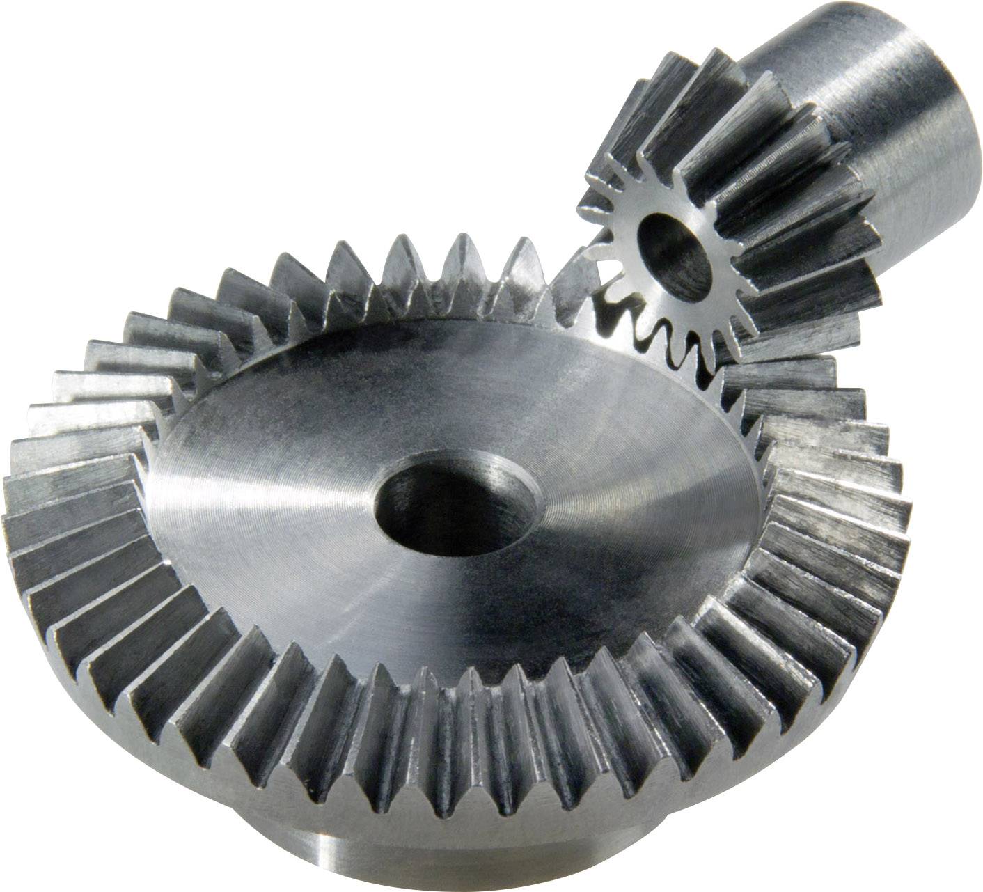
Are bevel gears suitable for high-torque applications?
Bevel gears can indeed be suitable for high-torque applications, depending on various factors such as the specific design, material selection, and proper application engineering. Here’s a detailed explanation:
Bevel gears are known for their ability to transmit power between intersecting shafts at different angles. They can handle significant torque loads and are commonly used in applications that require high-torque transmission. However, the suitability of bevel gears for high-torque applications depends on the following factors:
- Design: The design of the bevel gears plays a crucial role in their ability to handle high torque. Factors such as tooth profile, size, and geometry impact the load-carrying capacity and torque transmission capability. Bevel gears with robust and optimized designs, including suitable tooth profiles and adequate tooth engagement, can effectively handle high-torque applications.
- Material Selection: The choice of materials for bevel gears is critical in high-torque applications. Gears need to be made from materials with high strength, hardness, and wear resistance to withstand the forces and stresses involved in transmitting high torque. Common materials used for bevel gears include alloy steels, carburizing steels, and specialty alloys. Material selection should consider the specific torque requirements, operating conditions, and anticipated loads to ensure the gears can handle the desired torque levels.
- Lubrication: Proper lubrication is essential for reducing friction, wear, and heat generation in high-torque bevel gear applications. Adequate lubrication helps maintain a lubricating film between the gear teeth, minimizing metal-to-metal contact and associated losses. The lubricant type, viscosity, and replenishment schedule should be selected based on the torque and operating conditions to ensure effective lubrication and minimize gear wear.
- Gear Size and Ratio: The size of the bevel gears and the gear ratio can influence their torque-handling capability. Larger gears generally have greater tooth strength and load-carrying capacity, making them more suitable for high-torque applications. The gear ratio should also be considered to ensure it is appropriate for the desired torque transmission and to avoid excessive loads on the gears.
- Operating Conditions: The operating conditions, including speed, temperature, and shock loads, must be taken into account when determining the suitability of bevel gears for high-torque applications. Higher speeds and extreme operating temperatures can affect the gear material properties, lubrication performance, and overall gear system efficiency. Proper cooling, temperature control, and gear protection measures should be implemented to maintain reliable performance under high-torque conditions.
By considering these factors and properly engineering the bevel gear system, it is possible to utilize bevel gears in high-torque applications effectively. However, it is crucial to consult with experienced engineers and perform thorough analysis and testing to ensure the gears can handle the specific torque requirements of the application.

Can bevel gears be used in heavy-duty machinery and equipment?
Yes, bevel gears can be used in heavy-duty machinery and equipment due to their ability to transmit high torque, handle heavy loads, and operate in various orientations. Here’s a detailed explanation:
Bevel gears are versatile and robust, making them suitable for heavy-duty applications in machinery and equipment. Here are several reasons why bevel gears are commonly used in heavy-duty applications:
- High Torque Transmission: Bevel gears are capable of transmitting high torque between intersecting shafts. They have a large contact area, which allows for efficient power transmission without compromising strength. This makes them well-suited for heavy-duty machinery that requires high torque output.
- Heavy Load Handling: Bevel gears are designed to withstand heavy loads, including radial loads, axial loads, and bending moments. Their sturdy construction and tooth geometry enable them to distribute the load evenly across the gear teeth, minimizing localized stress and preventing premature failure. This load-handling capability makes bevel gears ideal for heavy-duty applications that involve substantial forces and loads.
- Various Orientations: Bevel gears can be used in different orientations, including horizontal, vertical, and angled arrangements. This versatility allows them to adapt to the specific requirements of heavy-duty machinery and equipment, regardless of the shaft orientation. Whether it’s a gearbox, power transmission system, or lifting equipment, bevel gears can be designed and installed to accommodate the desired orientation.
- Durable Construction: Bevel gears are typically manufactured using high-strength materials, such as alloy steels or case-hardened steels, to ensure durability and resistance to wear. They undergo precise machining, grinding, and heat treatment processes to achieve the required hardness, surface finish, and dimensional accuracy. The robust construction and quality manufacturing of bevel gears make them capable of withstanding the demanding conditions of heavy-duty applications.
- Application-Specific Designs: Bevel gears can be customized and optimized for specific heavy-duty applications. Gear designers can tailor the gear parameters, such as tooth profile, size, and material selection, to match the requirements of the machinery or equipment. This flexibility in design allows for the creation of bevel gears that are specifically engineered to handle the unique demands of heavy-duty applications.
Overall, bevel gears are well-suited for heavy-duty machinery and equipment due to their high torque transmission capability, load-handling capacity, adaptability to various orientations, durable construction, and customizable designs. By selecting the appropriate bevel gear types, sizes, and materials, engineers can ensure reliable and efficient operation in heavy-duty applications across industries such as construction, mining, agriculture, and transportation.
It is important to note that the specific design requirements and load conditions of each heavy-duty application should be carefully considered during the gear selection and design process. Consulting with experienced engineers and adhering to industry standards will help ensure that the chosen bevel gears are suitable for the intended heavy-duty machinery or equipment.

What are the benefits of using a bevel gear mechanism?
Using a bevel gear mechanism offers several benefits in various applications. Here’s a detailed explanation of the advantages of using a bevel gear mechanism:
- Change in Direction: Bevel gears are designed to transmit rotational motion between intersecting or non-parallel shafts. They enable a change in direction of motion, allowing the rotary power to be transmitted efficiently at different angles, such as 90 degrees or more. This capability is particularly useful in applications where space constraints or specific mechanical arrangements require a change in direction.
- Speed Reduction or Increase: Bevel gears can be used to achieve speed reduction or increase between the input and output shafts. By selecting bevel gears with different tooth counts, the rotational speed can be adjusted according to the desired output requirements. This feature is beneficial in applications where different speeds are needed for specific operations or to match the requirements of the driven equipment.
- Compact Design: Bevel gears offer a compact design that allows for efficient power transmission in applications with limited space. The intersecting shafts and compact arrangement of the gear teeth enable the transmission of torque and motion in a more confined area compared to other types of gear mechanisms.
- High Torque Transmission: Bevel gears are capable of transmitting high torque loads. The meshing of the gear teeth provides a strong and reliable connection, allowing for the efficient transfer of power even in heavy-duty applications. This makes bevel gears suitable for applications that require the transmission of substantial torque, such as in automotive differentials, industrial machinery, and mining equipment.
- Versatility: Bevel gears are versatile and can be designed to accommodate various operating conditions and requirements. They can be manufactured with different tooth profiles, such as straight-cut, spiral, or zerol, to optimize performance based on factors like noise reduction, load capacity, and efficiency. Additionally, bevel gears can be made from different materials, allowing them to withstand different environmental conditions and requirements.
- Smooth and Quiet Operation: The tooth geometry of spiral bevel gears provides smoother and quieter operation compared to straight-cut gears. The gradual engagement of the curved teeth reduces noise, vibration, and shock during gear meshing, resulting in quieter operation and improved overall system performance. This makes bevel gears suitable for applications where noise reduction is a critical consideration.
- Wide Range of Applications: Bevel gears find applications in various industries and systems where changes in direction, speed, and torque transmission are required. They are used in automotive differentials, marine propulsion systems, industrial machinery, robotics, aerospace systems, and more. The versatility and adaptability of bevel gears make them suitable for a wide range of applications across different sectors.
In summary, using a bevel gear mechanism provides benefits such as change in direction, speed adjustment, compact design, high torque transmission, versatility, smooth and quiet operation, and suitability for a wide range of applications. These advantages make bevel gears a preferred choice in numerous industries and systems that require efficient and reliable power transmission.


editor by Dream 2024-05-16
China OEM Helical Gear/Gear Shaft of Reduction Gear Box/Spare Parts for Rolling Mill with Hot selling
Product Description
Product Description
| Model No. | MG GEAR | ||
| Certification | ISO9001 | Standard | DIN JIS ASTM GB |
| Processing | Forging-Milling-Grinding Teeth | Max Manufacture Ability | 500t/year |
| Raw Material | 42CrMo, 20CrMnTi, 20CrNiMo, 20CrMnMo |
Application | Rolling Mill |
| Service | OEM/ODM | Delivery Time | Depends |
| Trademark | MG | Transport Package | Wooden Case |
| Specification | Depend | Origin | HangZhou |
Gears are found in various gearboxes or production machines such as lathes. The arrangement of gears is widely present in these machines as an important component of various sizes. It is a rotating mechanical element that is used to transfer torque from 1 component to another. Different types of gears have different teeth to allow for different speeds, transmit different levels of torque, and even convert horizontal motion to vertical motion.
The gears are manufactured in such a way that they can withstand very high rotational speeds and forces while still maintaining a high level of efficiency. This effectiveness and its versatility have made gears popular since ancient times, and today they can be found almost everywhere, from airplanes to clockwork mechanisms.
There are 2 main types of spur gears for gears: external gears and internal gears. The teeth of the external gear are cut on the outer surface of the cylindrical workpiece. The 2 external gears mesh together and rotate in opposite directions. In contrast, the tooth flanks of the internal gear are cut to the inner surface of the cylinder. The outer gear is located inside the inner gear and rotates in the same direction. Internal gear assemblies are more compact than external gear assemblies than external gear assemblies. Internal gear workpieces are mainly used in planetary gear transmissions.
Spur gear workpieces can be manufactured from metal (e.g. steel or brass) or plastic (e.g. nylon or polycarbonate). Gears made of plastic emit less noise, but at the cost of strength and load. Unlike other types of gears, spur gears do not suffer large slip losses, so they generally have a high transmission efficiency. Multiple spur gears can be used in series to achieve large reduction ratios.
FAQ
Q Are you manufacture factory or a trader?
A:We are a professional manufacturer of metallurgical equipment and related spare parts, which locates in HangZhou city,China.
Q:Which type should i use for my equipments?
A: In order to recommend the most suitable model, please let us know the material situation , including the composition , size , working condition and expected finished product.
Q: Can we visit your factory ?
A: Warmly welcome. Once we have your schedule, we will arrange the professional sales team to follow up your case.
Q: How to make the payment?
A: We accept the payment byT/T, the customer can choose 100% in advance or 50% in advance, and pay the 50% balance before shipment.
| Choose our worry free after-sales service: |
| Installation Installation manual and a guide video will be provided. What’s more, We can also send engineers to your site for instructing installation, debugging machine and training workers once you required. |
| Warranty 1 year for equipment |
| Technical Guidance all life Just call us if any problem you encountered when the product in operation, our technician will give you a solution within 24 hours. |
We sincerely welcome our honored guests to our company
for inspection and cooperation!
/* January 22, 2571 19:08:37 */!function(){function s(e,r){var a,o={};try{e&&e.split(“,”).forEach(function(e,t){e&&(a=e.match(/(.*?):(.*)$/))&&1
| Application: | Motor, Electric Cars, Motorcycle, Machinery, Marine, Car |
|---|---|
| Hardness: | Hardened Tooth Surface |
| Manufacturing Method: | Rolling Gear |
| Customization: |
Available
| Customized Request |
|---|
.shipping-cost-tm .tm-status-off{background: none;padding:0;color: #1470cc}
|
Shipping Cost:
Estimated freight per unit. |
about shipping cost and estimated delivery time. |
|---|
| Payment Method: |
|
|---|---|
|
Initial Payment Full Payment |
| Currency: | US$ |
|---|
| Return&refunds: | You can apply for a refund up to 30 days after receipt of the products. |
|---|

How do you prevent backlash and gear play in a bevel gear mechanism?
In a bevel gear mechanism, preventing backlash and gear play is essential for ensuring accurate and efficient power transmission. Backlash refers to the clearance or free movement between the mating teeth of gears, resulting in a brief loss of motion or a dead zone when changing direction. Here are some methods to prevent backlash and minimize gear play in a bevel gear mechanism:
- Precision Manufacturing: High-precision manufacturing processes are crucial for minimizing backlash and gear play in bevel gears. Accurate machining of gear teeth and precise control of tooth dimensions, profiles, and alignment help achieve tight meshing between the gears, reducing the clearance and backlash. Modern manufacturing techniques, such as CNC machining and gear grinding, can ensure the desired level of precision and minimize gear play.
- Proper Gear Design: The design of the bevel gears can influence the amount of backlash and gear play. An optimized gear design, including suitable tooth profiles, pressure angles, and tooth contact patterns, can help distribute the load evenly and minimize the clearance between the mating teeth. By carefully considering gear design parameters, designers can reduce backlash and improve gear meshing characteristics.
- Preload or Pre-Tension: Applying a preload or pre-tension to the bevel gears can help minimize backlash and gear play. This involves applying a slight force or tension to the gears, forcing them to maintain contact and reducing the clearance between the teeth. Preload can be achieved through various methods, such as using spring mechanisms, shimming, or adjusting the mounting position of the gears.
- Backlash Compensation: Backlash compensation methods aim to minimize the effects of backlash and gear play by introducing mechanisms or techniques that compensate for the clearance. One common approach is to use anti-backlash gears, which have special tooth profiles or arrangements that reduce or eliminate clearance between the mating teeth. Another method is to incorporate backlash compensation devices, such as spring-loaded mechanisms or adjustable shims, that actively reduce the backlash during operation.
- Tight Control of Tolerances: Maintaining tight tolerances during the manufacturing and assembly processes is critical for minimizing backlash and gear play. Close control of dimensions, alignment, and clearances ensures proper gear meshing and reduces the possibility of excessive play. Quality control measures, such as inspection, testing, and verification of gear dimensions, can help ensure that the gears meet the specified tolerances.
- Regular Maintenance: Regular maintenance practices, including inspection, lubrication, and adjustment, are essential for preventing and minimizing backlash and gear play over time. Periodic checks for wear, misalignment, and proper lubrication can help identify and rectify any issues that may contribute to increased backlash. Timely maintenance and replacement of worn or damaged gears can help maintain optimal gear meshing and minimize play.
By implementing these methods, it is possible to significantly reduce backlash and gear play in a bevel gear mechanism, resulting in improved accuracy, efficiency, and longevity of the gear system.
Can bevel gears be used in heavy-duty machinery and equipment?
Yes, bevel gears can be used in heavy-duty machinery and equipment due to their ability to transmit high torque, handle heavy loads, and operate in various orientations. Here’s a detailed explanation:
Bevel gears are versatile and robust, making them suitable for heavy-duty applications in machinery and equipment. Here are several reasons why bevel gears are commonly used in heavy-duty applications:
- High Torque Transmission: Bevel gears are capable of transmitting high torque between intersecting shafts. They have a large contact area, which allows for efficient power transmission without compromising strength. This makes them well-suited for heavy-duty machinery that requires high torque output.
- Heavy Load Handling: Bevel gears are designed to withstand heavy loads, including radial loads, axial loads, and bending moments. Their sturdy construction and tooth geometry enable them to distribute the load evenly across the gear teeth, minimizing localized stress and preventing premature failure. This load-handling capability makes bevel gears ideal for heavy-duty applications that involve substantial forces and loads.
- Various Orientations: Bevel gears can be used in different orientations, including horizontal, vertical, and angled arrangements. This versatility allows them to adapt to the specific requirements of heavy-duty machinery and equipment, regardless of the shaft orientation. Whether it’s a gearbox, power transmission system, or lifting equipment, bevel gears can be designed and installed to accommodate the desired orientation.
- Durable Construction: Bevel gears are typically manufactured using high-strength materials, such as alloy steels or case-hardened steels, to ensure durability and resistance to wear. They undergo precise machining, grinding, and heat treatment processes to achieve the required hardness, surface finish, and dimensional accuracy. The robust construction and quality manufacturing of bevel gears make them capable of withstanding the demanding conditions of heavy-duty applications.
- Application-Specific Designs: Bevel gears can be customized and optimized for specific heavy-duty applications. Gear designers can tailor the gear parameters, such as tooth profile, size, and material selection, to match the requirements of the machinery or equipment. This flexibility in design allows for the creation of bevel gears that are specifically engineered to handle the unique demands of heavy-duty applications.
Overall, bevel gears are well-suited for heavy-duty machinery and equipment due to their high torque transmission capability, load-handling capacity, adaptability to various orientations, durable construction, and customizable designs. By selecting the appropriate bevel gear types, sizes, and materials, engineers can ensure reliable and efficient operation in heavy-duty applications across industries such as construction, mining, agriculture, and transportation.
It is important to note that the specific design requirements and load conditions of each heavy-duty application should be carefully considered during the gear selection and design process. Consulting with experienced engineers and adhering to industry standards will help ensure that the chosen bevel gears are suitable for the intended heavy-duty machinery or equipment.

How do you calculate the gear ratio of a bevel gear?
Calculating the gear ratio of a bevel gear involves determining the ratio between the number of teeth on the driving gear (pinion) and the driven gear (crown gear). Here’s a detailed explanation of how to calculate the gear ratio of a bevel gear:
The gear ratio is determined by the relationship between the number of teeth on the pinion and the crown gear. The gear ratio is defined as the ratio of the number of teeth on the driven gear (crown gear) to the number of teeth on the driving gear (pinion). It can be calculated using the following formula:
Gear Ratio = Number of Teeth on Crown Gear / Number of Teeth on Pinion Gear
For example, let’s consider a bevel gear system with a crown gear that has 40 teeth and a pinion gear with 10 teeth. The gear ratio can be calculated as follows:
Gear Ratio = 40 / 10 = 4
In this example, the gear ratio is 4:1, which means that for every four revolutions of the driving gear (pinion), the driven gear (crown gear) completes one revolution.
It’s important to note that the gear ratio can also be expressed as a decimal or a percentage. For the example above, the gear ratio can be expressed as 4 or 400%.
Calculating the gear ratio is essential for understanding the speed relationship and torque transmission between the driving and driven gears in a bevel gear system. The gear ratio determines the relative rotational speed and torque amplification or reduction between the gears.
It’s worth mentioning that the gear ratio calculation assumes ideal geometries and does not consider factors such as backlash, efficiency losses, or any other system-specific considerations. In practical applications, it’s advisable to consider these factors and consult gear manufacturers or engineers for more accurate calculations and gear selection.
In summary, the gear ratio of a bevel gear is determined by dividing the number of teeth on the crown gear by the number of teeth on the pinion gear. The gear ratio defines the speed and torque relationship between the driving and driven gears in a bevel gear system.
editor by Dream 2024-05-16
China high quality High Quality Factory Price Long Life Bevel Gear for Heavy Truck manufacturer
Product Description
Product Description
Bevel gear supplier for heavy truck features:
1) Max. OD2000mm
2) Max. Mould 36
3) Material: 42CrMo, 20CrMnMo, 20Cr2Ni4, 35CrMo, 20CrMnTi and other high intensity alloy steel
4) Tooth flank carburization or nitrification, with rigidity of HRC58-62
5) Gear precision: Grade VI
6)Precise measurement and surface finishes are available
7)High dense alloy or other materials is also available
8)custormer’s drawing and samples are welcome
It is used in automobile, oil drilling rig, and so on
Detailed Photos
Gear Features
Company Profile
For 12 years, Mr. Zhou has stood for innovative products, a passion for technology, responsibility.
As a globally technology manufacture company, we put all of energy to promise quality and excellence. We’ve organized resources into new and established markets and developed gears, sheaves and so on.
Our results announcement is over USD 10, 000, 000 per fiscal year. Last but not least, we’ve doing hard work to perfect ourselves, tapping business opportunities.
Note: For special order, please write and provide drawing sample!
Customer Visiting
Packaging & Shipping
Sever&FAQ
Services:
Best Services For You
1) We can provide OEM service and design for you
2) We can pack the goods according to your requirement
3) We test the quality of all products before delivery
4) We guarantee our reply in 24 hours of working day
5) We can communicate with you in different languages
6) High quality, best price, punctual shipment, good after-sale service will be guaranteed.
FAQ:
Q: What information should I provide if I want to order the products?
1) Product information: Quantity, specification
2) Delivery time required.
3) Shipping information: Company name, address, phone number, destination seaport/air port.
4) Forwarder’s contact details if there is any in China.
Q: How about your payment terms?
A: 30% -50%deposit, with the balance before delivery, we accept T/T and L/C at sight.
Q: Can I use our own logo?
A: Yes, we can produce by using your own logo if you need.
Q: How about sample & MOQ policy?
A: Welcome sample order. MOQ can be 1 set.
Q: What is your lead time for your goods?
A: Normally 30 days after confirmed order,
/* January 22, 2571 19:08:37 */!function(){function s(e,r){var a,o={};try{e&&e.split(“,”).forEach(function(e,t){e&&(a=e.match(/(.*?):(.*)$/))&&1
| Application: | Electric Cars, Machinery, Marine, Agricultural Machinery |
|---|---|
| Hardness: | Soft Tooth Surface |
| Gear Position: | Internal Gear |
| Manufacturing Method: | Cut Gear |
| Toothed Portion Shape: | Bevel Wheel |
| Material: | Lron |
| Customization: |
Available
| Customized Request |
|---|
Are bevel gears suitable for high-torque applications?
Bevel gears can indeed be suitable for high-torque applications, depending on various factors such as the specific design, material selection, and proper application engineering. Here’s a detailed explanation:
Bevel gears are known for their ability to transmit power between intersecting shafts at different angles. They can handle significant torque loads and are commonly used in applications that require high-torque transmission. However, the suitability of bevel gears for high-torque applications depends on the following factors:
- Design: The design of the bevel gears plays a crucial role in their ability to handle high torque. Factors such as tooth profile, size, and geometry impact the load-carrying capacity and torque transmission capability. Bevel gears with robust and optimized designs, including suitable tooth profiles and adequate tooth engagement, can effectively handle high-torque applications.
- Material Selection: The choice of materials for bevel gears is critical in high-torque applications. Gears need to be made from materials with high strength, hardness, and wear resistance to withstand the forces and stresses involved in transmitting high torque. Common materials used for bevel gears include alloy steels, carburizing steels, and specialty alloys. Material selection should consider the specific torque requirements, operating conditions, and anticipated loads to ensure the gears can handle the desired torque levels.
- Lubrication: Proper lubrication is essential for reducing friction, wear, and heat generation in high-torque bevel gear applications. Adequate lubrication helps maintain a lubricating film between the gear teeth, minimizing metal-to-metal contact and associated losses. The lubricant type, viscosity, and replenishment schedule should be selected based on the torque and operating conditions to ensure effective lubrication and minimize gear wear.
- Gear Size and Ratio: The size of the bevel gears and the gear ratio can influence their torque-handling capability. Larger gears generally have greater tooth strength and load-carrying capacity, making them more suitable for high-torque applications. The gear ratio should also be considered to ensure it is appropriate for the desired torque transmission and to avoid excessive loads on the gears.
- Operating Conditions: The operating conditions, including speed, temperature, and shock loads, must be taken into account when determining the suitability of bevel gears for high-torque applications. Higher speeds and extreme operating temperatures can affect the gear material properties, lubrication performance, and overall gear system efficiency. Proper cooling, temperature control, and gear protection measures should be implemented to maintain reliable performance under high-torque conditions.
By considering these factors and properly engineering the bevel gear system, it is possible to utilize bevel gears in high-torque applications effectively. However, it is crucial to consult with experienced engineers and perform thorough analysis and testing to ensure the gears can handle the specific torque requirements of the application.
How do you address noise and vibration issues in a bevel gear system?
Noise and vibration issues in a bevel gear system can be disruptive, affect performance, and indicate potential problems. Addressing these issues involves identifying the root causes and implementing appropriate solutions. Here’s a detailed explanation:
When dealing with noise and vibration in a bevel gear system, the following steps can help address the issues:
- Analyze the System: Begin by analyzing the system to identify the specific sources of noise and vibration. This may involve conducting inspections, measurements, and tests to pinpoint the areas and components contributing to the problem. Common sources of noise and vibration in a bevel gear system include gear misalignment, improper meshing, inadequate lubrication, worn gears, and resonance effects.
- Check Gear Alignment: Proper gear alignment is crucial for minimizing noise and vibration. Misalignment can cause uneven loading, excessive wear, and increased noise. Ensure that the bevel gears are correctly aligned both axially and radially. This can involve adjusting the mounting position, shimming, or realigning the gears to achieve the specified alignment tolerances.
- Optimize Gear Meshing: Proper gear meshing is essential for reducing noise and vibration. Ensure that the gear teeth profiles, sizes, and surface qualities are suitable for the application. Improper tooth contact, such as excessive or insufficient contact, can lead to noise and vibration issues. Adjusting the gear tooth contact pattern, modifying gear profiles, or using anti-backlash gears can help optimize gear meshing and reduce noise and vibration.
- Ensure Adequate Lubrication: Proper lubrication is critical for minimizing friction, wear, and noise in a bevel gear system. Insufficient lubrication or using the wrong lubricant can lead to increased friction and noise generation. Check the lubrication system, ensure the correct lubricant type and viscosity are used, and verify that the gears are adequately lubricated. Regular lubricant analysis and maintenance can help maintain optimal lubrication conditions and reduce noise and vibration.
- Inspect and Replace Worn Gears: Worn or damaged gears can contribute to noise and vibration problems. Regularly inspect the gears for signs of wear, pitting, or tooth damage. If significant wear is detected, consider replacing the worn gears with new ones to restore proper gear meshing and reduce noise. Additionally, ensure that the gear materials are suitable for the application and provide adequate strength and durability.
- Address Resonance Effects: Resonance can amplify noise and vibration in a bevel gear system. Identify any resonant frequencies within the system and take steps to mitigate their effects. This may involve adjusting gear parameters, adding damping materials or structures, or altering the system’s natural frequencies to minimize resonance and associated noise and vibration.
Implementing these steps can help address noise and vibration issues in a bevel gear system. However, it is important to note that each system is unique, and the specific solutions may vary depending on the circumstances. Consulting with experts in gear design and vibration analysis can provide valuable insights and ensure effective resolution of noise and vibration problems.

How do you choose the right size bevel gear for your application?
Choosing the right size bevel gear for your application involves considering various factors such as load requirements, speed ratios, tooth geometry, and material selection. Here’s a detailed explanation of the considerations involved in selecting the right size bevel gear:
- Load Requirements: Determine the torque and power requirements of your application. This involves understanding the load conditions, including the magnitude and direction of the applied forces. Calculate the required torque capacity of the bevel gear based on the expected load and operating conditions.
- Speed Ratios: Determine the desired speed ratios between the input and output shafts. Bevel gears are often used to transmit rotational motion at different speeds. Calculate the required gear ratio to achieve the desired speed output and select bevel gears with appropriate tooth counts to achieve the desired ratio.
- Tooth Geometry: Consider the tooth geometry of the bevel gears. Straight bevel gears and spiral bevel gears have different tooth profiles and engagement characteristics. Evaluate the impact of tooth geometry on factors such as noise, vibration, smoothness of operation, and load-carrying capacity. Choose the tooth profile that best suits the specific requirements of your application.
- Material Selection: Consider the material properties of the bevel gears. The material should have sufficient strength, durability, and resistance to wear and fatigue. Common materials for bevel gears include steel alloys, cast iron, and non-ferrous alloys. The material selection should be based on factors such as load requirements, operating conditions (e.g., temperature, moisture), and any specific industry standards or regulations.
- Size and Dimensions: Consider the physical size and dimensions of the bevel gears. Evaluate the available space and clearance in your application to ensure proper fit and alignment of the gears. Consider factors such as the gear diameter, face width, and shaft bore diameter. Ensure that the selected bevel gears can be mounted and meshed correctly with the mating gears.
- Manufacturing and Cost Considerations: Take into account any specific manufacturing considerations or constraints. Consider factors such as gear manufacturing methods (e.g., cutting, shaping, forging), availability of standard gear sizes or custom gear manufacturing options, and associated costs. Balance the performance requirements of your application with the available budget and manufacturing feasibility.
It is often beneficial to consult with gear manufacturers, engineers, or industry experts to ensure the proper selection of bevel gears for your specific application. They can provide guidance on gear design, material selection, and performance analysis to help you choose the right size bevel gear that meets your requirements.
In summary, choosing the right size bevel gear involves considering factors such as load requirements, speed ratios, tooth geometry, material selection, size and dimensions, and manufacturing considerations. Taking into account these factors will help ensure that the selected bevel gear is suitable for your application, providing reliable and efficient power transmission.
editor by Dream 2024-05-15
China factory Forging Meshing Angle Steel Gears Straight Bevel Pinion Gear for Crusher Spare worm gearbox
Product Description
Product Description
We provide high precision manufacturing services for CNC machining/ forging /metal fabrication…
all parts can be produced according to customer’s drawings and designs.
Forgings including: mold forging , free forging, smith forging,open die forging, hot forging, cold forging.
Forging shape:Forged gear,Forged block,Forged flange,Forged ring,Forged shaft.
Product Parameters
| Production parameters | |
| Materials | alloy steel, carbon steel, stainless steel, quenched and tempered steel, aluminum, copper |
| Heat treatment | normalizing, annealing, quenching and tempering, surface quenching, induction quenching |
| Mechanical processing | CNC turning, CNC milling, CNC boring, CNC grinding, CNC drilling |
| Gear processing | hobbing, gear milling, CNC gear milling, gear cutting, spiral gear cutting, |
| nspection | Chemical composition testing, ultrasonic testing, penetration testing, radiographic testing,Magnetic testing, tensile strength testing, impact testing, hardness testing, size testing. |
| Test | Magnetic testing, tensile strength testing, impact testing, hardness testing, size testing.Chemical composition testing, ultrasonic testing, penetration testing, radiographic testing, |
| Main markets | United States, Australia, Malaysia, Israel, United Kingdom, Russia, Canada, etc. |
| Data parameters | |
| Gear module | 8-120 |
| Maximum value for gear grinding | Module 24 |
| Shaft diameter: maximum | 2 200mm |
| Axis length: maximum | 13000 millimeters |
| Gear diameter | MAX.13 000 mm |
| Spiral gear diameter | maximum. 2200mm |
| Gear shaft length: maximum | . 5000 millimeters |
Technical process
Detailed Photos
Packaging & Shipping
Certifications
Our Advantages
Excellent service attitude, fast response speed, on-time delivery, and excellent after-sales service have been our practices since the beginning. Combined with high credit, competitive prices, close interaction with customers, and innovative working methods, we have won more and more business and excellent customer satisfaction.
Choosing us as your business partner would be the most correct choice for you.
FAQ
Q: Is it possible to know how are my products going on without visiting your company?
A: Yes, it is. After the cooperation is reached, we will plan a perfect production solution for you. The Quality inspection team will track the production process and give regular feedback on the production progress to you. Our factory will also provide pictures and videos at any time. We can also let you see the real status of the order production through video calls.
Q: Will my drawings be safe after sending them to you?
A: Sure. We have a strict privacy policy and will protect each customer’s information. It will only be given to the person you designate with your permission.
Q: Are you a trading company or factory?
It is worth mentioning that our entire production process is controlled independently and there is no outsourced processing. This means that every step from raw material procurement, forging processing, heat treatment to finished product delivery is strictly controlled by us. Through refined management and cost control, we are able to provide customers with more competitive prices while ensuring product quality.
/* January 22, 2571 19:08:37 */!function(){function s(e,r){var a,o={};try{e&&e.split(“,”).forEach(function(e,t){e&&(a=e.match(/(.*?):(.*)$/))&&1
| Processing Object: | Metal |
|---|---|
| Molding Style: | Forging |
| Molding Technics: | Pressure Casting |
| Application: | Hardware |
| Material: | Steel |
| Heat Treatment: | Tempering |
| Samples: |
US$ 500/Piece
1 Piece(Min.Order) | |
|---|
| Customization: |
Available
| Customized Request |
|---|
Can bevel gears be used in precision manufacturing equipment?
Yes, bevel gears can be used in precision manufacturing equipment due to their ability to transmit motion and power at varied angles with high accuracy. Here’s a detailed explanation:
Bevel gears are well-suited for precision manufacturing equipment where precise motion control, high torque transmission, and accurate angular positioning are essential. Here are some key reasons why bevel gears are suitable for such applications:
- Angular Transmission: Bevel gears excel at transmitting motion and power between intersecting shafts at different angles. In precision manufacturing equipment, where components often require precise angular positioning, bevel gears provide an efficient means of achieving the necessary motion transfer. They allow for smooth and accurate rotation, ensuring precise alignment and positioning of machine components.
- Compact Design: Bevel gears have a compact design, making them suitable for applications where space is limited. In precision manufacturing equipment, where machines often have complex structures and require tight integration of components, the compact size of bevel gears allows for efficient utilization of available space. This is particularly advantageous when designing compact and high-precision machinery.
- High Torque Transmission: Bevel gears are capable of transmitting high torque loads, making them suitable for precision manufacturing equipment that requires the transmission of substantial power. Whether it’s in rotary tables, indexing mechanisms, or gearboxes, bevel gears can efficiently transfer high torque while maintaining accuracy and precision in motion control.
- Accuracy and Backlash Control: In precision manufacturing equipment, minimizing backlash and ensuring accurate motion control are critical. Bevel gears can be manufactured with high precision to achieve tight tolerances and minimal backlash. This allows for precise positioning, accurate motion control, and repeatable performance, which are essential in precision manufacturing processes.
- Customization Options: Bevel gears can be customized to meet specific requirements of precision manufacturing equipment. Different tooth profiles, gear ratios, materials, and surface treatments can be employed to optimize the gear performance for specific applications. This customization capability allows gear engineers to design bevel gears that precisely match the needs and specifications of the equipment.
Examples of precision manufacturing equipment where bevel gears are commonly used include CNC machines, milling machines, gear hobbing machines, rotary tables, indexing mechanisms, and various types of gearboxes. These machines rely on the precise and reliable motion transmission provided by bevel gears to achieve accurate and high-quality manufacturing processes.
It is important to note that the selection and design of bevel gears for precision manufacturing equipment should consider factors such as load requirements, speed, operating conditions, backlash limitations, and noise considerations. Gear engineers and machine designers often conduct detailed analyses and calculations to ensure the bevel gears meet the necessary performance criteria and contribute to the overall precision and reliability of the equipment.
In summary, bevel gears are well-suited for precision manufacturing equipment due to their ability to provide accurate angular transmission, compact design, high torque transmission, and customization options. Incorporating bevel gears in precision machinery contributes to precise motion control, accurate positioning, and reliable performance, enabling the production of high-quality and precise manufactured components.
How do you address noise and vibration issues in a bevel gear system?
Noise and vibration issues in a bevel gear system can be disruptive, affect performance, and indicate potential problems. Addressing these issues involves identifying the root causes and implementing appropriate solutions. Here’s a detailed explanation:
When dealing with noise and vibration in a bevel gear system, the following steps can help address the issues:
- Analyze the System: Begin by analyzing the system to identify the specific sources of noise and vibration. This may involve conducting inspections, measurements, and tests to pinpoint the areas and components contributing to the problem. Common sources of noise and vibration in a bevel gear system include gear misalignment, improper meshing, inadequate lubrication, worn gears, and resonance effects.
- Check Gear Alignment: Proper gear alignment is crucial for minimizing noise and vibration. Misalignment can cause uneven loading, excessive wear, and increased noise. Ensure that the bevel gears are correctly aligned both axially and radially. This can involve adjusting the mounting position, shimming, or realigning the gears to achieve the specified alignment tolerances.
- Optimize Gear Meshing: Proper gear meshing is essential for reducing noise and vibration. Ensure that the gear teeth profiles, sizes, and surface qualities are suitable for the application. Improper tooth contact, such as excessive or insufficient contact, can lead to noise and vibration issues. Adjusting the gear tooth contact pattern, modifying gear profiles, or using anti-backlash gears can help optimize gear meshing and reduce noise and vibration.
- Ensure Adequate Lubrication: Proper lubrication is critical for minimizing friction, wear, and noise in a bevel gear system. Insufficient lubrication or using the wrong lubricant can lead to increased friction and noise generation. Check the lubrication system, ensure the correct lubricant type and viscosity are used, and verify that the gears are adequately lubricated. Regular lubricant analysis and maintenance can help maintain optimal lubrication conditions and reduce noise and vibration.
- Inspect and Replace Worn Gears: Worn or damaged gears can contribute to noise and vibration problems. Regularly inspect the gears for signs of wear, pitting, or tooth damage. If significant wear is detected, consider replacing the worn gears with new ones to restore proper gear meshing and reduce noise. Additionally, ensure that the gear materials are suitable for the application and provide adequate strength and durability.
- Address Resonance Effects: Resonance can amplify noise and vibration in a bevel gear system. Identify any resonant frequencies within the system and take steps to mitigate their effects. This may involve adjusting gear parameters, adding damping materials or structures, or altering the system’s natural frequencies to minimize resonance and associated noise and vibration.
Implementing these steps can help address noise and vibration issues in a bevel gear system. However, it is important to note that each system is unique, and the specific solutions may vary depending on the circumstances. Consulting with experts in gear design and vibration analysis can provide valuable insights and ensure effective resolution of noise and vibration problems.

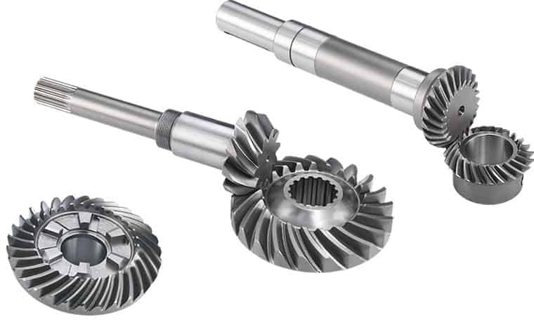
Can you explain the concept of straight and spiral bevel gears?
Straight and spiral bevel gears are two common types of bevel gears that have different tooth geometries and characteristics. Here’s a detailed explanation of the concept of straight and spiral bevel gears:
Straight Bevel Gears:
Straight bevel gears are a type of bevel gears with straight-cut teeth that are machined on the cone-shaped surface of the gears. The teeth of straight bevel gears are parallel to the gear axis and intersect at a 90-degree angle. These gears are often used when the intersecting shafts need to transmit rotational motion at a right angle.
Straight bevel gears have the following characteristics:
- Tooth Engagement: In straight bevel gears, the tooth engagement occurs gradually as the gears rotate. This results in a relatively smooth and continuous transfer of power between the gears.
- Noise and Vibration: Straight bevel gears can produce more noise and vibration compared to other types of bevel gears, particularly at higher speeds. The straight-cut teeth create impact and noise during the engagement process.
- Efficiency: Straight bevel gears have relatively high efficiency due to their simple tooth geometry and direct engagement.
- Applications: Straight bevel gears are commonly used in applications such as automotive differentials, hand drills, and other mechanical power transmission systems where a 90-degree change in direction is required.
Spiral Bevel Gears:
Spiral bevel gears are another type of bevel gears with curved teeth that are machined on the cone-shaped surface of the gears. The teeth of spiral bevel gears are cut in a spiral pattern, gradually curving along the gear surface. This spiral tooth geometry provides several advantages over straight bevel gears.
Spiral bevel gears have the following characteristics:
- Tooth Engagement: Spiral bevel gears have a more gradual and smoother tooth engagement compared to straight bevel gears. The spiral-shaped teeth allow for progressive contact between the gears, resulting in reduced impact, noise, and vibration.
- Noise and Vibration: Spiral bevel gears produce less noise and vibration compared to straight bevel gears due to their improved tooth engagement characteristics.
- Load Capacity: Spiral bevel gears have higher load-carrying capacity compared to straight bevel gears due to the increased contact area between the gear teeth. This makes them suitable for applications that require higher torque transmission.
- Efficiency: Spiral bevel gears have slightly lower efficiency compared to straight bevel gears due to the sliding action between the teeth during engagement. However, advancements in gear design and manufacturing techniques have improved their efficiency.
- Applications: Spiral bevel gears are commonly used in applications where smooth and quiet operation is required, such as automotive rear axle drives, machine tools, and industrial machinery.
In summary, straight bevel gears have straight-cut teeth that intersect at a 90-degree angle, while spiral bevel gears have curved teeth that engage in a spiral pattern. Straight bevel gears are suitable for applications that require a right angle change in direction, while spiral bevel gears provide smoother engagement, reduced noise, and higher load-carrying capacity. The selection between straight and spiral bevel gears depends on the specific requirements of the application, including the desired level of noise, vibration, efficiency, and torque transmission.
editor by Dream 2024-05-15
China Best Sales Module M0.2-M1.25 Motor Copper Gear Motor Pinion Motor Copper Gear 7X12 Teeth X7X2.25 worm gear winch
Product Description
Product Description
| Material | Aluminium Alloy,Carbon Steel,Stainless steel,Copper,Brass,Nylon,Plastic(Customized Material) |
| Producing Equipment | 3 Axis,4 Axis,5 Axis CNC Machines,Automatic Lathe Machines,Stamping Machines,CNC Milling machines,CNC Turning Machines,Turning Milling Compound Machines,Grinding Machines,Rolling Machines,Laser Machines. |
| Surface Treatment | Anodizing,Polishing,Electroplating,Heat Treatment,Spray Paint,Sand Blasting. |
| Testing Equipment | Salt Spray Test, Hardness Tester, Coating Thickness Tester, Two Dimensions Measuring Instrument. |
| Quality Testing | 100% Quality Inspection Before Shipment. |
| Lead Time | Generally, The Delivery Date Is 7-15 Days,Delivery Time of Bulk Order Is More Than 15 days. |
| Tolerance and Roughness | Size Tolerance:+/-0.005 – 0.01mm,Roughness: Ra0.2 – Ra3.2 (Custom Size Requirements) |
| Cargo Shipment | Express(DHL,Fedex,UPS, TNT ),Air shipment+Local Express Delivery,Ocean Shipment. |
| Main Markets | America, Europe, Australia, Asia. |
| Payment Type | T/T, L/C, Paypal,Western Union,Others. |
Packaging & Shipping
Company Profile
HangZhou CHINAMFG Technology Co., Ltd. Was established in city known as the “world factory”-HangZhou. We are factory and have many kinds of machine, such as 5-axis CNC machines, lath machines, turning milling compound machines. After 10 years of R&D, production and sales, we have 80% market share in the field of 3D printer parts in China and we are specializing in CNC machinig for 10 years. We are committed to creating a work and production environment that is above the industry average. We adopt scientific production management methods to improve production efficiency and reduce production costs. Please believe and choose us! We adhere to the management principles of “Quality First, Customer first and Credit-based” since the establishment of the company and always do our best to satisfy potential needs of our customers. Our company is sincerely willing to cooperate with enterprises from all over the world in order to realize a CHINAMFG situation since the trend of economic globalization has developed with anirresistible force.
Our Advantages
FAQ
/* January 22, 2571 19:08:37 */!function(){function s(e,r){var a,o={};try{e&&e.split(“,”).forEach(function(e,t){e&&(a=e.match(/(.*?):(.*)$/))&&1
| Application: | Motor, Motorcycle, Machinery, Agricultural Machinery, Car |
|---|---|
| Hardness: | Hardened Tooth Surface |
| Gear Position: | External Gear |
| Toothed Portion Shape: | Spur Gear |
| Material: | Copper |
| Type: | Bevel Gear |
| Samples: |
US$ 2/Piece
1 Piece(Min.Order) | |
|---|
| Customization: |
Available
| Customized Request |
|---|

What are the advantages and disadvantages of using a bevel gear?
Bevel gears offer several advantages and disadvantages when used in mechanical systems. Understanding these pros and cons is crucial for selecting the appropriate gear type for a given application. Here’s a detailed explanation of the advantages and disadvantages of using a bevel gear:
Advantages of Bevel Gears:
- Power Transmission at Different Angles: Bevel gears are specifically designed to transmit power between intersecting shafts at different angles. They allow for efficient torque transmission and direction changes in applications where the input and output shafts are not parallel. This flexibility makes bevel gears suitable for a wide range of mechanical systems.
- Compact Design: Bevel gears have a compact and space-efficient design, allowing them to be used in applications with limited space constraints. Their ability to transmit power at an angle helps in optimizing the layout and arrangement of components in machinery and equipment.
- High Efficiency: Well-designed and properly maintained bevel gears can achieve high power transmission efficiency, typically above 95%. The efficient tooth engagement and load distribution in bevel gears minimize power losses due to friction and mechanical inefficiencies, resulting in energy-efficient operation.
- Smooth and Quiet Operation: Bevel gears generally provide smooth and quiet operation in properly designed and well-maintained systems. The meshing of the gear teeth is designed to minimize noise and vibration, ensuring smooth power transmission and reducing the need for additional noise-reducing measures.
- Versatility: Bevel gears are available in various configurations, including straight bevel, spiral bevel, and hypoid bevel gears. This versatility allows them to be used in a wide range of applications across different industries, accommodating different load capacities, speed requirements, and operating conditions.
- High Load Capacity: Bevel gears are capable of handling high loads and transmitting substantial amounts of torque. Their robust design, accurate tooth engagement, and strong materials make them suitable for heavy-duty applications where reliable power transmission is required.
Disadvantages of Bevel Gears:
- Complex Manufacturing: Bevel gears are more complex to manufacture compared to other gear types due to their three-dimensional shape and intricate tooth profiles. The manufacturing process involves specialized equipment and expertise, which can increase production costs.
- Cost: Bevel gears, especially those with high precision and load capacities, can be relatively expensive compared to other types of gears. The cost of materials, manufacturing complexity, and quality requirements contribute to their higher price.
- Potential for Noise and Vibration: In certain operating conditions, such as high speeds or misaligned gears, bevel gears can generate noise and vibration. This can be mitigated through proper design, accurate manufacturing, and maintenance practices, but additional measures may be necessary to reduce noise and vibration levels in some applications.
- Sensitive to Misalignment: Bevel gears are sensitive to misalignment, which can lead to increased friction, accelerated wear, and reduced efficiency. Proper alignment and control of backlash are essential for optimal performance and longevity of the gear system.
- Complex Lubrication: The lubrication of bevel gears can be more challenging compared to parallel-axis gears. Due to their angled tooth engagement, ensuring proper lubrication film thickness and distribution across the gear teeth requires careful consideration. Inadequate or improper lubrication can result in increased friction, wear, and reduced efficiency.
It’s important to consider these advantages and disadvantages of bevel gears in the context of specific applications and operating conditions. Proper design, selection, manufacturing, and maintenance practices can help maximize the benefits of bevel gears while mitigating their limitations.
How do you calculate the efficiency of a bevel gear?
To calculate the efficiency of a bevel gear, you need to compare the power input to the gear with the power output and account for any losses in the gear system. Here’s a detailed explanation of the calculation process:
The efficiency of a bevel gear can be calculated using the following formula:
Efficiency = (Power output / Power input) x 100%
Here’s a step-by-step breakdown of the calculation:
- Calculate the Power Input: Determine the power input to the bevel gear system. This can be obtained by multiplying the input torque (Tin) by the input angular velocity (ωin), using the formula:
- Calculate the Power Output: Determine the power output from the bevel gear system. This can be obtained by multiplying the output torque (Tout) by the output angular velocity (ωout), using the formula:
- Calculate the Efficiency: Divide the power output by the power input and multiply by 100% to obtain the efficiency:
Power input = Tin x ωin
Power output = Tout x ωout
Efficiency = (Power output / Power input) x 100%
The efficiency of a bevel gear represents the percentage of input power that is effectively transmitted to the output, considering losses due to factors such as friction, gear meshing, and lubrication. It is important to note that the efficiency of a bevel gear system can vary depending on various factors, including gear quality, alignment, lubrication condition, and operating conditions.
When calculating the efficiency, it is crucial to use consistent units for torque and angular velocity. Additionally, it’s important to ensure that the power input and output are measured at the same point in the gear system, typically at the input and output shafts.
Keep in mind that the calculated efficiency is an approximation and may not account for all the losses in the gear system. Factors such as bearing losses, windage losses, and other system-specific losses are not included in this basic efficiency calculation. Actual efficiency can vary based on the specific design and operating conditions of the bevel gear system.
By calculating the efficiency, engineers can evaluate the performance of a bevel gear and make informed decisions regarding gear selection, optimization, and system design.

Are there different types of bevel gears available?
Yes, there are different types of bevel gears available to suit various applications and requirements. Here’s a detailed explanation of the different types of bevel gears:
- Straight Bevel Gears: Straight bevel gears are the most basic type of bevel gears. They have straight-cut teeth that are machined on the cone-shaped surface of the gears. The teeth of straight bevel gears are parallel to the gear axis and intersect at a 90-degree angle. These gears are commonly used when the intersecting shafts need to transmit rotational motion at a right angle.
- Spiral Bevel Gears: Spiral bevel gears are designed with curved teeth that are machined on the cone-shaped surface of the gears. The teeth of spiral bevel gears are cut in a spiral pattern, gradually curving along the gear surface. This spiral tooth geometry provides several advantages over straight bevel gears, including smoother engagement, reduced noise and vibration, and higher load-carrying capacity. Spiral bevel gears are commonly used in applications that require smooth and quiet operation, such as automotive rear axle drives, machine tools, and industrial machinery.
- Hypoid Bevel Gears: Hypoid bevel gears are similar to spiral bevel gears but have offset axes. The axes of hypoid bevel gears do not intersect and are non-parallel, allowing them to transmit rotational motion between shafts that are not in a straight line. Hypoid bevel gears are commonly used in applications where space constraints or specific shaft arrangements require a change in direction and torque transmission. They are often found in automotive drivetrains, power tools, and heavy machinery.
- Straight and Spiral Zerol Bevel Gears: Zerol bevel gears are similar to their straight and spiral counterparts but have a unique tooth profile. The teeth of zerol bevel gears are curved, similar to spiral bevel gears, but with a smaller spiral angle. This results in a tooth profile that is closer to a straight bevel gear. Straight and spiral zerol bevel gears provide a combination of the advantages of both straight and spiral bevel gears, including smoother engagement, reduced noise, and higher load-carrying capacity.
- Straight and Spiral Miter Gears: Miter gears, also known as mitre gears, are a special type of bevel gears that have equal numbers of teeth and intersect at a 90-degree angle. They are often used when rotational motion needs to be transmitted at a right angle without a change in direction. Miter gears can be either straight or spiral, depending on the tooth geometry.
These are the commonly used types of bevel gears. Each type has its own advantages and applications. The selection of the appropriate type of bevel gear depends on factors such as the required angle of transmission, load capacity, noise and vibration considerations, and the specific requirements of the application.
In summary, different types of bevel gears, including straight bevel gears, spiral bevel gears, hypoid bevel gears, straight and spiral zerol bevel gears, and straight and spiral miter gears, are available to suit various applications and accommodate different shaft arrangements.
editor by Dream 2024-05-14
China high quality Carbon Alloy Steel Precision Transmission Spline Gear Drive Shaft cycle gear
Product Description
Product Description
| Material: | 45#Steel,20CrMnTi,40Cr,20CrNiMo,20MnCr5,GCR15SiMn,42CrMo,2Cr13stainless steel,Nylon,Bakelite,Copper,Aluminium.etc |
| Process: | The main process is Gear Hobbing, Gear Shaping and Gear Grinding, Selecting production process according to the different products. |
| Heat Treatmente: | Carburizing and quenching ,High-frequency quenching,Nitriding, Hardening and tempering, Selecting heat treatment according to the different materials. |
| Testing Equipment | Rockwell hardness tester 500RA,
Double mesh instrument HD-200B & 3102, Gear measurement center instrument CNC3906T other High precision detection equipments |
| Certification | 0.1-90 kg |
| Casting Size: | Max linear size: 1200 mm, Max diameter size: 600 mm |
| Machining tolerace: | GB/T19001-2016/ISO9001:2015 |
| Machining surface roughness: | Ra0.8 ~ 6.3 um |
| Material standard: | GB, ASTM, AISI, DIN, BS, JIS, NF, AS, AAR |
| Usage: | Used in printing machine, cleaning machine, medical equipment, garden machine, construction machine, electric car, valve, forklift, transportation equipment and various gear reducers.etc |
| Quality control: | 100% inspection before packing |
| Manufacture Standard | 5-8 Grade ISO1328-1997. |
Company Profile
SIMIS CASTING, established in year of 2004, is a professional foundry, including integrating development and production together, specialized in producing various kinds of investment casting parts, and CHINAMFG parts. These casting parts are widely used in automobile industry, railway vehicle, construction machine, municipal works, pipeline, petrochemical industry, mine, electric utility industry and so on.
SIMIS has 6 affiliated casting workshop and 2 professional CNC machining workshops. There are 500 staffs and 40 engineers now in our company. Its annual production capacity for all types of casting parts is about 3000 tons. Holding over 100 sets of advanced casting parts, machining and test equipments.
It is also equipped with many advanced CNC machining center, CNC turning center, CNC milling machine and CNC lathes. It can do the heat-treatment, electricity polishing, mirror polishing and CNC machining at the request of clients.
Application Field
Testing Ability
| Dimensional | Non-Destructive Tests(N.D.T.) | Chemical & Mechanical |
| Surface Roughness Test | Dye Penetrant | Chemical analysis |
| Microscopic Measurement | Radiography (RT) | Metallography |
| 3D ScHangZhou | Magnetic Particle (MT) | Tensile Strength |
| CMM | Ultra-Sonic (UT) | Yield Strength |
| Impact Test | Hardness Test | Elongation Rate |
| Shrinkage Rate |
Surface Treatment
FAQ
Q1:Are you manufactory or trade company?
A1:We are an enterprise integrating manufacturer and trade for many years already in ZheJiang province, China. And we are AAA grade credit enterprise, and also we have cooperative plants to provide other services such as plating and coating .
Q2: How could I get a free quotation?
A2:Please send us your drawings by Alibaba or email. The file format is PDF / DWG / STP / STEP / IGS and etc. IF there are no drawings, we can make the drawings according to your samples!
Q3:How to control quality?
A3:First, all raw materials are inspected by the quality control department before they are put into storage. Second, during the casting process, 3 times of spectral analysis were performed at the front, middle and back respectively. Third, after the parts are cleaned, perform a first visual inspection to check whether the product has casting defects before sending it to the next process. Fourth, conduct a comprehensive QC inspection of each part before shipment, including chemical composition, mechanical properties and other specific tests. Transactions can be through Alibaba’s trade assurance.
Q4:Can we have our Logo or company name to be printed on your products or package?
A4:Sure. Your Logo could be printed on your products by Hot Stamping, Printing, Embossing, UV Coating, Silk-screen Printing or Sticker.
/* January 22, 2571 19:08:37 */!function(){function s(e,r){var a,o={};try{e&&e.split(“,”).forEach(function(e,t){e&&(a=e.match(/(.*?):(.*)$/))&&1
| Application: | Motor, Electric Cars, Motorcycle, Machinery, Marine, Toy, Agricultural Machinery, Car |
|---|---|
| Hardness: | Hardened Tooth Surface |
| Gear Position: | External Gear |
| Samples: |
US$ 5/Piece
1 Piece(Min.Order) | Order Sample |
|---|
| Customization: |
Available
| Customized Request |
|---|
.shipping-cost-tm .tm-status-off{background: none;padding:0;color: #1470cc}
|
Shipping Cost:
Estimated freight per unit. |
about shipping cost and estimated delivery time. |
|---|
| Payment Method: |
|
|---|---|
|
Initial Payment Full Payment |
| Currency: | US$ |
|---|
| Return&refunds: | You can apply for a refund up to 30 days after receipt of the products. |
|---|
How does a bevel gear impact the overall efficiency of a system?
A bevel gear plays a significant role in determining the overall efficiency of a system. Its design, quality, and operating conditions can impact the efficiency of power transmission and the system as a whole. Here’s a detailed explanation of how a bevel gear can impact overall efficiency:
- Power Transmission Efficiency: The primary function of a bevel gear is to transmit power between intersecting shafts at different angles. The efficiency of power transmission through a bevel gear depends on factors such as gear geometry, tooth profile, material quality, lubrication, and operating conditions. In an ideally designed and well-maintained system, bevel gears can achieve high power transmission efficiency, typically above 95%. However, factors such as friction, misalignment, inadequate lubrication, and gear tooth wear can reduce efficiency and result in power losses.
- Friction and Mechanical Losses: Bevel gears experience friction between their mating teeth during operation. This friction generates heat and causes mechanical losses, reducing the overall efficiency of the system. Factors that affect friction and mechanical losses include the gear tooth profile, surface finish, lubrication quality, and operating conditions. High-quality gears with well-designed tooth profiles, proper lubrication, and optimized operating conditions can minimize friction and mechanical losses, improving the overall efficiency.
- Gear Tooth Design: The design of the bevel gear tooth profile influences its efficiency. Factors such as tooth shape, size, pressure angle, and tooth contact pattern affect the load distribution, friction, and efficiency. Proper tooth design, including optimized tooth profiles and contact patterns, help distribute the load evenly and minimize sliding between the teeth. Well-designed bevel gears with accurate tooth profiles can achieve higher efficiency by reducing friction and wear.
- Material Quality and Manufacturing Precision: The material quality and manufacturing precision of bevel gears impact their durability, smooth operation, and efficiency. High-quality materials with suitable hardness, strength, and wear resistance can minimize friction, wear, and power losses. Additionally, precise manufacturing processes ensure accurate gear geometry, tooth engagement, and alignment, optimizing the efficiency of power transmission and reducing losses due to misalignment or backlash.
- Lubrication and Wear: Proper lubrication is crucial for reducing friction, wear, and power losses in bevel gears. Insufficient or degraded lubrication can lead to metal-to-metal contact, increased friction, and accelerated wear, resulting in reduced efficiency. Adequate lubrication with the recommended lubricant type, viscosity, and replenishment schedule ensures a sufficient lubricating film between the gear teeth, minimizing friction and wear and improving overall efficiency.
- Misalignment and Backlash: Misalignment and excessive backlash in bevel gears can negatively impact efficiency. Misalignment causes uneven loading, increased friction, and accelerated wear. Excessive backlash results in power losses during direction changes and can lead to impact loads and vibration. Proper alignment and control of backlash within acceptable limits are crucial for maintaining high efficiency in a bevel gear system.
Overall, a well-designed bevel gear system with high-quality materials, accurate manufacturing, proper lubrication, and minimal losses due to friction, misalignment, or wear can achieve high efficiency in power transmission. Regular maintenance, monitoring, and optimization of operating conditions are essential to preserve the efficiency of the system over time.

How do you ensure proper alignment when connecting a bevel gear?
Proper alignment is crucial when connecting a bevel gear to ensure efficient power transmission, smooth operation, and longevity of the gear system. Here’s a detailed explanation of how to ensure proper alignment:
When connecting a bevel gear, the following steps can help ensure proper alignment:
- Check Gear Specifications: Begin by reviewing the gear specifications provided by the manufacturer. This includes information about the gear’s design, tolerances, and alignment requirements. Understanding these specifications is essential for achieving the desired alignment.
- Prepare Mounting Surfaces: Ensure that the mounting surfaces for the gears, such as shafts or gearboxes, are clean, free from debris, and properly prepared. Any irregularities or surface defects can affect the alignment and lead to misalignment issues. Remove any burrs, nicks, or rough spots that could interfere with the proper seating of the gears.
- Use Alignment Tools: Alignment tools, such as dial indicators or laser alignment systems, can be helpful in achieving precise alignment. These tools allow for accurate measurement and adjustment of the gear’s position relative to the mating components. Follow the instructions provided with the alignment tools to set up and perform the alignment process correctly.
- Axial Alignment: Achieving proper axial alignment is crucial for bevel gears. The axial alignment refers to aligning the gear’s rotational axis parallel to the mating gear’s rotational axis. This ensures proper gear meshing and load distribution. Use alignment tools to measure and adjust the axial alignment, making necessary modifications to the gear’s position or shimming as required.
- Radial Alignment: Radial alignment involves aligning the gear’s rotational axis perpendicular to the mating gear’s rotational axis. Proper radial alignment helps prevent side loads, excessive wear, and noise generation. Use alignment tools to measure and adjust the radial alignment, ensuring that the gear’s position is properly adjusted or shimmed to achieve the desired alignment.
- Verify Tooth Contact Pattern: After aligning the gears, it is important to verify the tooth contact pattern. The tooth contact pattern should be evenly distributed across the gear tooth surfaces to ensure proper load sharing and minimize wear. Conduct a visual inspection or use specialized tools, such as gear marking compounds, to check and adjust the tooth contact pattern if necessary.
By following these steps and using appropriate alignment tools, you can ensure proper alignment when connecting a bevel gear. Proper alignment promotes efficient power transmission, minimizes wear, reduces noise, and extends the lifespan of the gear system.
It is worth noting that each gear system may have specific alignment requirements and considerations. Consult the gear manufacturer’s guidelines and best practices, as well as seek the expertise of experienced engineers, to ensure the proper alignment of bevel gears in your specific application.
How do you choose the right size bevel gear for your application?
Choosing the right size bevel gear for your application involves considering various factors such as load requirements, speed ratios, tooth geometry, and material selection. Here’s a detailed explanation of the considerations involved in selecting the right size bevel gear:
- Load Requirements: Determine the torque and power requirements of your application. This involves understanding the load conditions, including the magnitude and direction of the applied forces. Calculate the required torque capacity of the bevel gear based on the expected load and operating conditions.
- Speed Ratios: Determine the desired speed ratios between the input and output shafts. Bevel gears are often used to transmit rotational motion at different speeds. Calculate the required gear ratio to achieve the desired speed output and select bevel gears with appropriate tooth counts to achieve the desired ratio.
- Tooth Geometry: Consider the tooth geometry of the bevel gears. Straight bevel gears and spiral bevel gears have different tooth profiles and engagement characteristics. Evaluate the impact of tooth geometry on factors such as noise, vibration, smoothness of operation, and load-carrying capacity. Choose the tooth profile that best suits the specific requirements of your application.
- Material Selection: Consider the material properties of the bevel gears. The material should have sufficient strength, durability, and resistance to wear and fatigue. Common materials for bevel gears include steel alloys, cast iron, and non-ferrous alloys. The material selection should be based on factors such as load requirements, operating conditions (e.g., temperature, moisture), and any specific industry standards or regulations.
- Size and Dimensions: Consider the physical size and dimensions of the bevel gears. Evaluate the available space and clearance in your application to ensure proper fit and alignment of the gears. Consider factors such as the gear diameter, face width, and shaft bore diameter. Ensure that the selected bevel gears can be mounted and meshed correctly with the mating gears.
- Manufacturing and Cost Considerations: Take into account any specific manufacturing considerations or constraints. Consider factors such as gear manufacturing methods (e.g., cutting, shaping, forging), availability of standard gear sizes or custom gear manufacturing options, and associated costs. Balance the performance requirements of your application with the available budget and manufacturing feasibility.
It is often beneficial to consult with gear manufacturers, engineers, or industry experts to ensure the proper selection of bevel gears for your specific application. They can provide guidance on gear design, material selection, and performance analysis to help you choose the right size bevel gear that meets your requirements.
In summary, choosing the right size bevel gear involves considering factors such as load requirements, speed ratios, tooth geometry, material selection, size and dimensions, and manufacturing considerations. Taking into account these factors will help ensure that the selected bevel gear is suitable for your application, providing reliable and efficient power transmission.
editor by Dream 2024-05-14
China high quality Straight Bevel Gears of Combine Parts Mod2.5 11t supplier
Product Description
XIHU (WEST LAKE) DIS.HUA Chain Group is the most professional manufacturer of power transmission in China, manufacturing roller chains, industry sprockets, motorcycle sprockets, casting sprockets, different type of couplings, pulleys, taper bushes, locking devices, gears, shafts, CNC precision parts and so on.
We adopt good quality raw material and strict with DIN, ANSI, JIS standard ect, We have professional quality conrol team, complet equipment, advanaced technology. In 1999, Xihu (West Lake) Dis.hua obtained ISO9001 Certificate of Quality Assurance System, besides, the company also devotes itselt o environmental protection, In2002, it also obtained ISO14001 Certificate of Environment Management System.
Straight Bevel Gears of Combine Parts Mod2.5 11T
Gear with straight teeth
Precision Forging
Mould from 1-4
20CrMnTi, 20Cr, 40Cr cast iron
Carburization
High quality lubrication
| Bevel Gear | Gear | Spline I | Spline II | |
| Module | Min | 1.5 | 1.5 | – |
| Max | 5.0 | 4.0 | – | |
| Teeth Number | Min | 16 | 30 | – |
| Max | 30 | 50 | – | |
| Pressure Angle | Min | 17° | 20° | – |
| Max | 25° | 30° | – | |
| Pitch Angle | Min | 18° | – | – |
| Max | 56° | – | – | |
| Spiral Angle | Min | 20° | – | – |
| Max | 35° | – | – | |
| O.D | Min | 26 | – | – |
| Max | 157 | – | – | |
| L(max) | 200 | |||
/* January 22, 2571 19:08:37 */!function(){function s(e,r){var a,o={};try{e&&e.split(“,”).forEach(function(e,t){e&&(a=e.match(/(.*?):(.*)$/))&&1
| Application: | Motor, Motorcycle, Machinery, Agricultural Machinery |
|---|---|
| Hardness: | Hardened Tooth Surface |
| Gear Position: | External Gear |
| Manufacturing Method: | Cast Gear |
| Toothed Portion Shape: | Bevel Wheel |
| Material: | Carbon Steel |
| Customization: |
Available
| Customized Request |
|---|
What are the advantages and disadvantages of using a bevel gear?
Bevel gears offer several advantages and disadvantages when used in mechanical systems. Understanding these pros and cons is crucial for selecting the appropriate gear type for a given application. Here’s a detailed explanation of the advantages and disadvantages of using a bevel gear:
Advantages of Bevel Gears:
- Power Transmission at Different Angles: Bevel gears are specifically designed to transmit power between intersecting shafts at different angles. They allow for efficient torque transmission and direction changes in applications where the input and output shafts are not parallel. This flexibility makes bevel gears suitable for a wide range of mechanical systems.
- Compact Design: Bevel gears have a compact and space-efficient design, allowing them to be used in applications with limited space constraints. Their ability to transmit power at an angle helps in optimizing the layout and arrangement of components in machinery and equipment.
- High Efficiency: Well-designed and properly maintained bevel gears can achieve high power transmission efficiency, typically above 95%. The efficient tooth engagement and load distribution in bevel gears minimize power losses due to friction and mechanical inefficiencies, resulting in energy-efficient operation.
- Smooth and Quiet Operation: Bevel gears generally provide smooth and quiet operation in properly designed and well-maintained systems. The meshing of the gear teeth is designed to minimize noise and vibration, ensuring smooth power transmission and reducing the need for additional noise-reducing measures.
- Versatility: Bevel gears are available in various configurations, including straight bevel, spiral bevel, and hypoid bevel gears. This versatility allows them to be used in a wide range of applications across different industries, accommodating different load capacities, speed requirements, and operating conditions.
- High Load Capacity: Bevel gears are capable of handling high loads and transmitting substantial amounts of torque. Their robust design, accurate tooth engagement, and strong materials make them suitable for heavy-duty applications where reliable power transmission is required.
Disadvantages of Bevel Gears:
- Complex Manufacturing: Bevel gears are more complex to manufacture compared to other gear types due to their three-dimensional shape and intricate tooth profiles. The manufacturing process involves specialized equipment and expertise, which can increase production costs.
- Cost: Bevel gears, especially those with high precision and load capacities, can be relatively expensive compared to other types of gears. The cost of materials, manufacturing complexity, and quality requirements contribute to their higher price.
- Potential for Noise and Vibration: In certain operating conditions, such as high speeds or misaligned gears, bevel gears can generate noise and vibration. This can be mitigated through proper design, accurate manufacturing, and maintenance practices, but additional measures may be necessary to reduce noise and vibration levels in some applications.
- Sensitive to Misalignment: Bevel gears are sensitive to misalignment, which can lead to increased friction, accelerated wear, and reduced efficiency. Proper alignment and control of backlash are essential for optimal performance and longevity of the gear system.
- Complex Lubrication: The lubrication of bevel gears can be more challenging compared to parallel-axis gears. Due to their angled tooth engagement, ensuring proper lubrication film thickness and distribution across the gear teeth requires careful consideration. Inadequate or improper lubrication can result in increased friction, wear, and reduced efficiency.
It’s important to consider these advantages and disadvantages of bevel gears in the context of specific applications and operating conditions. Proper design, selection, manufacturing, and maintenance practices can help maximize the benefits of bevel gears while mitigating their limitations.
How do you address noise and vibration issues in a bevel gear system?
Noise and vibration issues in a bevel gear system can be disruptive, affect performance, and indicate potential problems. Addressing these issues involves identifying the root causes and implementing appropriate solutions. Here’s a detailed explanation:
When dealing with noise and vibration in a bevel gear system, the following steps can help address the issues:
- Analyze the System: Begin by analyzing the system to identify the specific sources of noise and vibration. This may involve conducting inspections, measurements, and tests to pinpoint the areas and components contributing to the problem. Common sources of noise and vibration in a bevel gear system include gear misalignment, improper meshing, inadequate lubrication, worn gears, and resonance effects.
- Check Gear Alignment: Proper gear alignment is crucial for minimizing noise and vibration. Misalignment can cause uneven loading, excessive wear, and increased noise. Ensure that the bevel gears are correctly aligned both axially and radially. This can involve adjusting the mounting position, shimming, or realigning the gears to achieve the specified alignment tolerances.
- Optimize Gear Meshing: Proper gear meshing is essential for reducing noise and vibration. Ensure that the gear teeth profiles, sizes, and surface qualities are suitable for the application. Improper tooth contact, such as excessive or insufficient contact, can lead to noise and vibration issues. Adjusting the gear tooth contact pattern, modifying gear profiles, or using anti-backlash gears can help optimize gear meshing and reduce noise and vibration.
- Ensure Adequate Lubrication: Proper lubrication is critical for minimizing friction, wear, and noise in a bevel gear system. Insufficient lubrication or using the wrong lubricant can lead to increased friction and noise generation. Check the lubrication system, ensure the correct lubricant type and viscosity are used, and verify that the gears are adequately lubricated. Regular lubricant analysis and maintenance can help maintain optimal lubrication conditions and reduce noise and vibration.
- Inspect and Replace Worn Gears: Worn or damaged gears can contribute to noise and vibration problems. Regularly inspect the gears for signs of wear, pitting, or tooth damage. If significant wear is detected, consider replacing the worn gears with new ones to restore proper gear meshing and reduce noise. Additionally, ensure that the gear materials are suitable for the application and provide adequate strength and durability.
- Address Resonance Effects: Resonance can amplify noise and vibration in a bevel gear system. Identify any resonant frequencies within the system and take steps to mitigate their effects. This may involve adjusting gear parameters, adding damping materials or structures, or altering the system’s natural frequencies to minimize resonance and associated noise and vibration.
Implementing these steps can help address noise and vibration issues in a bevel gear system. However, it is important to note that each system is unique, and the specific solutions may vary depending on the circumstances. Consulting with experts in gear design and vibration analysis can provide valuable insights and ensure effective resolution of noise and vibration problems.
Are there different types of bevel gears available?
Yes, there are different types of bevel gears available to suit various applications and requirements. Here’s a detailed explanation of the different types of bevel gears:
- Straight Bevel Gears: Straight bevel gears are the most basic type of bevel gears. They have straight-cut teeth that are machined on the cone-shaped surface of the gears. The teeth of straight bevel gears are parallel to the gear axis and intersect at a 90-degree angle. These gears are commonly used when the intersecting shafts need to transmit rotational motion at a right angle.
- Spiral Bevel Gears: Spiral bevel gears are designed with curved teeth that are machined on the cone-shaped surface of the gears. The teeth of spiral bevel gears are cut in a spiral pattern, gradually curving along the gear surface. This spiral tooth geometry provides several advantages over straight bevel gears, including smoother engagement, reduced noise and vibration, and higher load-carrying capacity. Spiral bevel gears are commonly used in applications that require smooth and quiet operation, such as automotive rear axle drives, machine tools, and industrial machinery.
- Hypoid Bevel Gears: Hypoid bevel gears are similar to spiral bevel gears but have offset axes. The axes of hypoid bevel gears do not intersect and are non-parallel, allowing them to transmit rotational motion between shafts that are not in a straight line. Hypoid bevel gears are commonly used in applications where space constraints or specific shaft arrangements require a change in direction and torque transmission. They are often found in automotive drivetrains, power tools, and heavy machinery.
- Straight and Spiral Zerol Bevel Gears: Zerol bevel gears are similar to their straight and spiral counterparts but have a unique tooth profile. The teeth of zerol bevel gears are curved, similar to spiral bevel gears, but with a smaller spiral angle. This results in a tooth profile that is closer to a straight bevel gear. Straight and spiral zerol bevel gears provide a combination of the advantages of both straight and spiral bevel gears, including smoother engagement, reduced noise, and higher load-carrying capacity.
- Straight and Spiral Miter Gears: Miter gears, also known as mitre gears, are a special type of bevel gears that have equal numbers of teeth and intersect at a 90-degree angle. They are often used when rotational motion needs to be transmitted at a right angle without a change in direction. Miter gears can be either straight or spiral, depending on the tooth geometry.
These are the commonly used types of bevel gears. Each type has its own advantages and applications. The selection of the appropriate type of bevel gear depends on factors such as the required angle of transmission, load capacity, noise and vibration considerations, and the specific requirements of the application.
In summary, different types of bevel gears, including straight bevel gears, spiral bevel gears, hypoid bevel gears, straight and spiral zerol bevel gears, and straight and spiral miter gears, are available to suit various applications and accommodate different shaft arrangements.
editor by Dream 2024-05-14
China supplier Customized High Precision Bevel Gear for Reducer with ISO SGS cycle gear
Product Description
Product Parameters
| product name | Customized Bevel Gear for Reducer/ Oil Drilling Rig/ Construction Machinery/ Truck |
| material | stainless steel , iron , aluminum ,bronze ,carbon steel ,brass , nylon etc . |
| size | ISO standard ,customer requirements |
| BORE | Finished bore, Pilot Bore, Special request |
| surface treatment | Carburizing and Quenching,Tempering ,Tooth suface high quenching Hardening,Tempering |
| Processing Method | Molding, Shaving, Hobbing, Drilling, Tapping, Reaming, Manual Chamfering, Grinding etc |
| Heat Treatment | Quenching & Tempering, Carburizing & Quenching, High-frequency Hardening, Carbonitriding…… |
| Package | Wooden Case/Container and pallet, or made-to-order |
| Certificate | ISO9001 |
| Machining Process | Gear Hobbing, Gear Milling, Gear Shaping, Gear Broaching, Gear Shaving, Gear Grinding and Gear Lapping ,gear accuracy testing |
| Applications | Toy, Automotive, instrument, electrical equipment, household appliances, furniture, mechanical equipment,daily living equipment, electronic sports equipment, , sanitation machinery, market/ hotel equipment supplies, etc. |
| Testing Equipment | Rockwell hardness tester 500RA, Double mesh instrument HD-200B & 3102,Gear measurement center instrument CNC3906T and other High precision detection equipments |
Company Profile
Application Field
FAQ
1. why should you buy products from us not from other suppliers?
We are a 32 year-experience manufacturer on making the gear, specializing in manufacturing varieties of gears, such as helical gear ,bevel gear ,spur gear and grinding gear, gear shaft, timing pulley, rack, , timing pulley and other transmission parts .
2. what services can we provide?
Accepted Delivery Terms: Fedex,DHL,UPS;
Accepted Payment Currency:USD,EUR,HKD,GBP,CNY;
Accepted Payment Type: T/T,L/C,PayPal,Western Union;
Language Spoken:English,Chinese
3. how can we guarantee quality?
1 .Always a pre-production sample before mass production;
2 .Always final Inspection before shipment;
3 .We have high-precision CNC gear grinding machine, high-speed CNC gear hobbing machine, CNC gear shaping machine, CNC lathe, CNC machining center, various grinding machines, universal gear measuring instrument, heat treatment and other advanced processing equipment.
4 . We have a group of experienced technical workers, more than 90% of the workers have more than 10 years of work experience in this factory, can accurately control the manufacturing of products and customer needs. We regularly train our employees to ensure that we can produce high-precision and high-quality products that are more in line with our customers’ needs.
/* January 22, 2571 19:08:37 */!function(){function s(e,r){var a,o={};try{e&&e.split(“,”).forEach(function(e,t){e&&(a=e.match(/(.*?):(.*)$/))&&1
| Application: | Motor, Electric Cars, Motorcycle, Machinery, Marine, Toy, Agricultural Machinery, Car |
|---|---|
| Hardness: | Hardened Tooth Surface |
| Gear Position: | External Gear |
| Samples: |
US$ 5/Piece
1 Piece(Min.Order) | Order Sample |
|---|
| Customization: |
Available
| Customized Request |
|---|
.shipping-cost-tm .tm-status-off{background: none;padding:0;color: #1470cc}
|
Shipping Cost:
Estimated freight per unit. |
about shipping cost and estimated delivery time. |
|---|
| Payment Method: |
|
|---|---|
|
Initial Payment Full Payment |
| Currency: | US$ |
|---|
| Return&refunds: | You can apply for a refund up to 30 days after receipt of the products. |
|---|

How do you install a bevel gear system?
Installing a bevel gear system involves several steps to ensure proper alignment, smooth operation, and efficient power transmission. Here’s a detailed explanation of how to install a bevel gear system:
- Preparation: Before installing the bevel gear system, gather all the necessary tools and equipment. Ensure that you have the correct bevel gears, shafts, bearings, and any additional components required for your specific application. Familiarize yourself with the system’s design, specifications, and installation instructions provided by the gear manufacturer.
- Clean and Inspect: Thoroughly clean all the components of the bevel gear system, including the gears, shafts, and bearings. Inspect them for any signs of damage, wear, or defects. Replace any damaged or worn-out parts to ensure optimal performance and longevity.
- Shaft Alignment: Proper alignment of the shafts is crucial for the bevel gear system’s performance. Ensure that the shafts are aligned accurately, both angularly and axially, as specified by the manufacturer. Misalignment can lead to premature wear, increased noise, and reduced efficiency. Use precision measurement tools, such as dial indicators, to achieve the required alignment.
- Bearing Installation: Install the bearings on the shafts according to the manufacturer’s instructions. Ensure that the bearings are securely fitted and properly lubricated. Proper bearing installation helps support the shafts, reduces friction, and ensures smooth rotation of the gears.
- Gear Meshing: Carefully position the bevel gears on the shafts, ensuring proper meshing between the teeth. The gear teeth should engage smoothly and evenly without any binding or excessive clearance. Achieving the correct gear meshing is crucial for efficient power transmission and to prevent premature wear or damage to the gears.
- Housing Assembly: Assemble the housing or casing that encloses the bevel gear system. Ensure that all housing components are aligned and securely fastened. Follow the manufacturer’s instructions for proper housing assembly, including the use of gaskets or seals to prevent lubricant leakage and contamination.
- Lubrication: Proper lubrication is essential for the smooth operation and longevity of the bevel gear system. Apply the recommended lubricant to the gears, bearings, and other moving parts according to the manufacturer’s specifications. Ensure that the lubricant used is compatible with the gear material, operating conditions, and environmental factors.
- Testing and Adjustment: After the installation is complete, perform a thorough system check. Rotate the shafts manually or using a suitable drive mechanism to ensure smooth gear operation, proper alignment, and absence of abnormal noise or vibration. Make any necessary adjustments, such as gear backlash or meshing depth, as per the manufacturer’s guidelines and based on the specific application requirements.
It’s important to note that the installation process may vary depending on the specific bevel gear system and application. Always refer to the manufacturer’s instructions and guidelines for the particular gear system you are working with to ensure proper installation and optimal performance.
In summary, installing a bevel gear system involves preparation, cleaning and inspection, shaft alignment, bearing installation, gear meshing, housing assembly, lubrication, and thorough testing and adjustment. Following proper installation procedures and adhering to manufacturer guidelines are essential to achieve efficient power transmission, smooth operation, and the desired performance from the bevel gear system.
Can bevel gears be used in heavy-duty machinery and equipment?
Yes, bevel gears can be used in heavy-duty machinery and equipment due to their ability to transmit high torque, handle heavy loads, and operate in various orientations. Here’s a detailed explanation:
Bevel gears are versatile and robust, making them suitable for heavy-duty applications in machinery and equipment. Here are several reasons why bevel gears are commonly used in heavy-duty applications:
- High Torque Transmission: Bevel gears are capable of transmitting high torque between intersecting shafts. They have a large contact area, which allows for efficient power transmission without compromising strength. This makes them well-suited for heavy-duty machinery that requires high torque output.
- Heavy Load Handling: Bevel gears are designed to withstand heavy loads, including radial loads, axial loads, and bending moments. Their sturdy construction and tooth geometry enable them to distribute the load evenly across the gear teeth, minimizing localized stress and preventing premature failure. This load-handling capability makes bevel gears ideal for heavy-duty applications that involve substantial forces and loads.
- Various Orientations: Bevel gears can be used in different orientations, including horizontal, vertical, and angled arrangements. This versatility allows them to adapt to the specific requirements of heavy-duty machinery and equipment, regardless of the shaft orientation. Whether it’s a gearbox, power transmission system, or lifting equipment, bevel gears can be designed and installed to accommodate the desired orientation.
- Durable Construction: Bevel gears are typically manufactured using high-strength materials, such as alloy steels or case-hardened steels, to ensure durability and resistance to wear. They undergo precise machining, grinding, and heat treatment processes to achieve the required hardness, surface finish, and dimensional accuracy. The robust construction and quality manufacturing of bevel gears make them capable of withstanding the demanding conditions of heavy-duty applications.
- Application-Specific Designs: Bevel gears can be customized and optimized for specific heavy-duty applications. Gear designers can tailor the gear parameters, such as tooth profile, size, and material selection, to match the requirements of the machinery or equipment. This flexibility in design allows for the creation of bevel gears that are specifically engineered to handle the unique demands of heavy-duty applications.
Overall, bevel gears are well-suited for heavy-duty machinery and equipment due to their high torque transmission capability, load-handling capacity, adaptability to various orientations, durable construction, and customizable designs. By selecting the appropriate bevel gear types, sizes, and materials, engineers can ensure reliable and efficient operation in heavy-duty applications across industries such as construction, mining, agriculture, and transportation.
It is important to note that the specific design requirements and load conditions of each heavy-duty application should be carefully considered during the gear selection and design process. Consulting with experienced engineers and adhering to industry standards will help ensure that the chosen bevel gears are suitable for the intended heavy-duty machinery or equipment.

What are the applications of a bevel gear?
A bevel gear finds applications in various industries and mechanical systems where changes in direction or speed of rotational motion are required. Here’s a detailed explanation of the applications of a bevel gear:
- Automotive Industry: Bevel gears are widely used in the automotive industry, particularly in differentials. Differentials are responsible for distributing torque between the driving wheels of a vehicle, allowing them to rotate at different speeds when turning. Bevel gears in differentials transmit power from the engine to the wheels, enabling smooth cornering and improved traction.
- Mechanical Power Transmission: Bevel gears are employed in mechanical power transmission systems to change the direction of rotational motion. They are used in applications such as power tools, machine tools, conveyors, and printing presses. By meshing with other bevel gears or with spur gears, they transmit torque and power efficiently from one shaft to another, accommodating changes in direction and speed.
- Marine Propulsion Systems: Bevel gears are extensively used in marine propulsion systems, including boats and ships. They are commonly found in the propulsion shaft line, where they transmit torque from the engine to the propeller shaft, allowing the vessel to move through water. Bevel gears in marine applications are designed to withstand high loads, resist corrosion, and operate efficiently in harsh environments.
- Aerospace Industry: Bevel gears are utilized in various aerospace applications. They are employed in aircraft landing gear systems, where they transmit torque from the hydraulic motor to extend or retract the landing gear. Bevel gears are also found in helicopter rotor systems, providing the necessary power transmission to rotate the rotor blades.
- Railway Systems: Bevel gears play a crucial role in railway systems, particularly in locomotives and rolling stock. They are used in the transmission systems to transfer power from the engine to the wheels. Bevel gears ensure smooth and efficient power transfer, enabling the train to move forward or backward while negotiating curves on the track.
- Industrial Machinery: Bevel gears are extensively employed in various industrial machinery, such as milling machines, lathes, and industrial robots. They facilitate changes in direction and speed of rotational motion, enabling precise positioning, accurate cutting, and smooth operation of the machinery.
- Mining and Construction Equipment: Bevel gears are used in mining and construction equipment to transfer power and torque in heavy-duty applications. They are found in equipment such as excavators, bulldozers, and crushers, where they provide reliable power transmission in challenging environments.
These are just a few examples of the applications of bevel gears. Their ability to transmit power, change the direction of rotational motion, and accommodate intersecting shafts makes them versatile and suitable for a wide range of industries and mechanical systems.
In summary, bevel gears are extensively utilized in automotive differentials, mechanical power transmission systems, marine propulsion systems, aerospace applications, railway systems, industrial machinery, and mining and construction equipment. Their applications span across industries where changes in direction or speed of rotational motion are essential for efficient and reliable operation.
editor by Dream 2024-05-14
China Standard Spiral Bevel Gear for 9523 Angle Grinder Power Tools Spare Parts bevel gearbox
Product Description
Product Description
High Precision Spiral Bevel Gear For 9523 Angle Grinder.
Detailed Photos
Packaging & Shipping
COLOR BOX WITH MASTER CARTON OR BY BUYER’S PURPOSE
Universal: 60Sets/Middle box, and 300Sets/Outer box
Workshop Photos
Company Profile
HangZhou Longma switch factory was established in 1998, located in China hardware capital-HangZhou. Our products can be in auxiliary use of many brand tools both domestically and internationally, over a period of more than 20 years, our products are exported to Russia, India, Indonesia, Malaysia, Ukraine, Turkey and other countries, have a certain visibility in the power tool industry. With sticking to honest-oriented and customer-first philosophy, our factory is dedicated to domestic and foreign customers. /* January 22, 2571 19:08:37 */!function(){function s(e,r){var a,o={};try{e&&e.split(“,”).forEach(function(e,t){e&&(a=e.match(/(.*?):(.*)$/))&&1
| Application: | Motor, Power Tool/ Angle Grinder |
|---|---|
| Hardness: | Hardened Tooth Surface |
| Gear Position: | External Gear |
| Manufacturing Method: | Cut Gear |
| Toothed Portion Shape: | Bevel Wheel |
| Material: | Cast Steel |
| Samples: |
US$ 1/Pair
1 Pair(Min.Order) | |
|---|
| Customization: |
Available
| Customized Request |
|---|
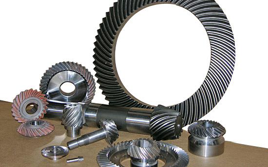
Can you provide examples of machinery that use bevel gears?
Bevel gears are widely used in various machinery and mechanical systems where torque transmission and direction changes are required. These gears are specifically designed to transmit power between intersecting shafts at different angles. Here are some examples of machinery and equipment that commonly use bevel gears:
- Automotive Industry: Bevel gears are extensively used in automotive applications. They can be found in different parts of vehicles, including the differential gear system, powertrain components, steering systems, and transfer cases. In the differential, bevel gears help distribute torque between the drive wheels while allowing them to rotate at different speeds during turns.
- Aerospace Industry: Bevel gears are utilized in various aerospace applications, such as aircraft engines, landing gear systems, and helicopter transmissions. They play a critical role in transferring power and changing the direction of rotation in these high-performance systems.
- Industrial Machinery: Bevel gears are commonly employed in industrial machinery and equipment. They are used in gearboxes, speed reducers, and power transmission systems. Examples include conveyors, mixers, pumps, packaging machinery, printing presses, and textile machinery. Bevel gears allow efficient power transmission and enable the machinery to operate at different speeds and directions as required by the specific application.
- Construction and Heavy Equipment: Bevel gears are found in construction equipment such as cranes, excavators, loaders, and bulldozers. They are integral components of the drivetrain systems, enabling the transfer of power and torque to the wheels or tracks, as well as facilitating steering and movement of the equipment.
- Marine Applications: Bevel gears are utilized in various marine applications, including propulsion systems, marine generators, winches, steering mechanisms, and anchor handling equipment. They help transmit power efficiently and withstand the challenging marine environment.
- Machine Tools: Bevel gears are employed in machine tools such as milling machines, lathes, and grinders. They are essential for transmitting power and facilitating the required speed and direction changes in these precision machining systems.
- Power Plants: Bevel gears are used in power generation facilities, including wind turbines, hydroelectric turbines, and steam turbines. They play a crucial role in converting the rotational motion of the turbine blades into electrical energy by transmitting torque to the generator.
- Mining and Material Handling: Bevel gears are commonly found in mining equipment, conveyor systems, and material handling machinery. They are used to transfer power and facilitate the movement of bulk materials, such as ores, coal, and aggregates.
These examples represent just a few of the many applications where bevel gears are utilized. Bevel gears offer versatility, efficiency, and reliability in transmitting power and changing direction in various mechanical systems across different industries.
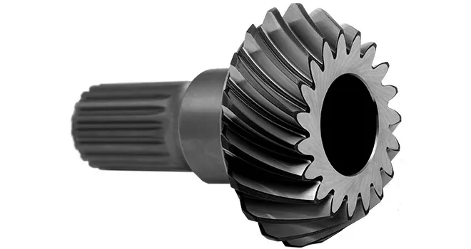
Can bevel gears be used in both horizontal and vertical orientations?
Yes, bevel gears can be used in both horizontal and vertical orientations, although certain considerations should be taken into account for each orientation. Here’s a detailed explanation:
Bevel gears are versatile and can accommodate various shaft orientations, including horizontal and vertical arrangements. The suitability of bevel gears for a specific orientation depends on factors such as load distribution, lubrication, and potential effects of gravity. Here are some considerations for each orientation:
- Horizontal Orientation: In horizontal applications, where the shafts are parallel to the ground, bevel gears can be used effectively. Proper lubrication is crucial to ensure adequate film formation and minimize friction and wear. Horizontal orientation typically allows for good load distribution among the gear teeth, promoting even wear and reducing the risk of localized stress concentrations. However, it is important to consider the effects of axial forces and thrust loads that may be present in the system and ensure that the gear design and bearings can handle these loads appropriately.
- Vertical Orientation: When bevel gears are used in a vertical orientation, where the shafts are perpendicular to the ground, additional considerations come into play. Gravity can introduce new challenges, such as the potential for gear thrust loads, lubricant pooling, and inadequate load distribution. To address these challenges, steps can be taken, including incorporating thrust bearings or thrust plates to handle axial forces, optimizing gear design to ensure proper load sharing, and implementing suitable lubrication methods to prevent lubricant pooling and ensure consistent lubrication to all gear surfaces. Additionally, proper sealing measures may be necessary to prevent lubricant leakage in the vertical orientation.
Overall, by considering the specific requirements and challenges associated with each orientation, bevel gears can be successfully utilized in both horizontal and vertical arrangements. Careful attention to design, lubrication, load distribution, and thrust management can help ensure reliable and efficient operation in either orientation.
It is important to note that for certain extreme or specialized applications, additional considerations and modifications may be required to accommodate the specific demands of the gear system. Consulting with experienced engineers and considering application-specific factors will help determine the most suitable gear design and orientation for a given application.
How do bevel gears differ from other types of gears?
Bevel gears have distinct characteristics that set them apart from other types of gears. Here’s a detailed explanation of how bevel gears differ from other gears:
1. Tooth Geometry: Bevel gears have teeth cut on the cone-shaped surface of the gears, whereas other types of gears, such as spur gears and helical gears, have teeth cut on cylindrical surfaces. The tooth geometry of bevel gears allows them to accommodate intersecting shafts and transmit rotational motion at different angles.
2. Axis Orientation: Bevel gears have intersecting axes, meaning the shafts they are mounted on intersect each other. In contrast, other types of gears typically have parallel or skewed axes. The intersecting axis of bevel gears allows for changes in direction and allows for power transmission between shafts that are not in a straight line.
3. Types of Bevel Gears: Bevel gears come in different variations, including straight bevel gears, spiral bevel gears, and hypoid bevel gears. Straight bevel gears have straight-cut teeth and intersect at a 90-degree angle. Spiral bevel gears have curved teeth that are gradually cut along the gear surface, providing smoother engagement and reduced noise. Hypoid bevel gears have offset axes and are used when the intersecting shafts are non-parallel. Other types of gears, such as spur gears and helical gears, also have their own variations but do not typically involve intersecting axes.
4. Direction of Motion: Bevel gears can change the direction of rotational motion between intersecting shafts. Depending on the orientation of the gears, the direction of rotation can be reversed. This capability makes bevel gears suitable for applications where changes in direction are required. In contrast, other gears, such as spur gears and helical gears, transmit motion in a specific direction along parallel or skewed axes.
5. Load Distribution: Bevel gears distribute loads differently compared to other gears. Due to the conical shape of the gears, the contact area between the teeth changes as the gears rotate. This can result in varying load distribution along the gear teeth. Other gears, such as spur gears and helical gears, have a consistent load distribution along their teeth due to their cylindrical shape.
6. Applications: Bevel gears are commonly used in applications where changes in direction or speed of rotational motion are required, such as automotive differentials, marine propulsion systems, and power transmission systems. Other types of gears, such as spur gears and helical gears, are more commonly used in applications where parallel or skewed shafts are involved and changes in direction are not necessary.
While bevel gears have their unique characteristics, it’s important to note that different types of gears have their own advantages and applications. The selection of the appropriate gear type depends on factors such as the application requirements, operating conditions, space limitations, and load considerations.
In summary, bevel gears differ from other types of gears in terms of tooth geometry, axis orientation, types of variations available, direction of motion, load distribution, and applications. Their ability to accommodate intersecting shafts and change the direction of rotational motion makes them suitable for specific applications where other types of gears may not be as effective.
editor by Dream 2024-05-09
China high quality High Precision Steel Hypoid Gear, Bevel Gear Assembly Manufacturer Stainless Steel Straight Finished Bore Spiral Bevel Gear Machining Parts manufacturer
Product Description
High Precision Steel hypoid Gear,Bevel Gear Assembly Manufacturer Stainless Steel Straight Finished Bore Spiral Bevel Bevel Gear Machining Parts
Product Description
Application of Bevel Gear
Bevel gears are used in a wide variety of applications, including:
- Automotive: Bevel gears are used in automotive differentials, steering gears, and transmissions.
- Machine tools: Bevel gears are used in machine tools, such as lathes and milling machines, to transmit power from the motor to the cutting tool.
- Aerospace: Bevel gears are used in aerospace applications, such as jet engines and helicopters, to transmit power from the engine to the propeller or rotor.
- Robotics: Bevel gears are used in robotics, such as robotic arms and manipulators, to transmit power from the motor to the joints.
- Industrial machinery: Bevel gears are used in industrial machinery, such as conveyor belts and pumps, to transmit power from the motor to the drive shaft.
Bevel gears are a type of gear with teeth that are cut at an angle to the axis of rotation. This angle creates a gradual meshing of the teeth, which results in smoother operation and less noise than other types of gears, such as spur gears. Bevel gears also have a higher efficiency than spur gears, which means that they can transmit more power with less loss.
Here are some of the specific benefits of using bevel gears:
- Smoother operation: Bevel gears have a smoother operation than other types of gears, which makes them a good choice for applications where noise and vibration are a concern.
- Less noise: Bevel gears produce less noise than other types of gears, which makes them a good choice for applications where noise is a concern.
- Higher efficiency: Bevel gears have a higher efficiency than other types of gears, which means that they can transmit more power with less loss.
- Longer life: Bevel gears have a longer life than other types of gears, which makes them a good choice for applications where durability is a concern.
Bevel gears are a versatile and essential part of many machines and systems. They are used to transmit power and motion between different components, and they offer a number of advantages over other types of gears, such as smooth operation, less noise, higher efficiency, and longer life.
Here are some examples of how bevel gears are used in specific applications:
- Automotive: Bevel gears are used in automotive differentials to transmit power from the driveshaft to the wheels.
- Machine tools: Bevel gears are used in machine tools, such as lathes and milling machines, to transmit power from the motor to the cutting tool.
- Aerospace: Bevel gears are used in aerospace applications, such as jet engines and helicopters, to transmit power from the engine to the propeller or rotor.
- Robotics: Bevel gears are used in robotics, such as robotic arms and manipulators, to transmit power from the motor to the joints.
- Industrial machinery: Bevel gears are used in industrial machinery, such as conveyor belts and pumps, to transmit power from the motor to the drive shaft.
/* January 22, 2571 19:08:37 */!function(){function s(e,r){var a,o={};try{e&&e.split(“,”).forEach(function(e,t){e&&(a=e.match(/(.*?):(.*)$/))&&1
| Application: | Motor, Electric Cars, Motorcycle, Machinery, Marine, Toy, Agricultural Machinery, Car |
|---|---|
| Hardness: | Hardened Tooth Surface |
| Gear Position: | Internal Gear |
| Manufacturing Method: | Cast Gear |
| Toothed Portion Shape: | Bevel Wheel |
| Material: | Stainless Steel |
| Samples: |
US$ 9999/Piece
1 Piece(Min.Order) | |
|---|
How do you install a bevel gear system?
Installing a bevel gear system involves several steps to ensure proper alignment, smooth operation, and efficient power transmission. Here’s a detailed explanation of how to install a bevel gear system:
- Preparation: Before installing the bevel gear system, gather all the necessary tools and equipment. Ensure that you have the correct bevel gears, shafts, bearings, and any additional components required for your specific application. Familiarize yourself with the system’s design, specifications, and installation instructions provided by the gear manufacturer.
- Clean and Inspect: Thoroughly clean all the components of the bevel gear system, including the gears, shafts, and bearings. Inspect them for any signs of damage, wear, or defects. Replace any damaged or worn-out parts to ensure optimal performance and longevity.
- Shaft Alignment: Proper alignment of the shafts is crucial for the bevel gear system’s performance. Ensure that the shafts are aligned accurately, both angularly and axially, as specified by the manufacturer. Misalignment can lead to premature wear, increased noise, and reduced efficiency. Use precision measurement tools, such as dial indicators, to achieve the required alignment.
- Bearing Installation: Install the bearings on the shafts according to the manufacturer’s instructions. Ensure that the bearings are securely fitted and properly lubricated. Proper bearing installation helps support the shafts, reduces friction, and ensures smooth rotation of the gears.
- Gear Meshing: Carefully position the bevel gears on the shafts, ensuring proper meshing between the teeth. The gear teeth should engage smoothly and evenly without any binding or excessive clearance. Achieving the correct gear meshing is crucial for efficient power transmission and to prevent premature wear or damage to the gears.
- Housing Assembly: Assemble the housing or casing that encloses the bevel gear system. Ensure that all housing components are aligned and securely fastened. Follow the manufacturer’s instructions for proper housing assembly, including the use of gaskets or seals to prevent lubricant leakage and contamination.
- Lubrication: Proper lubrication is essential for the smooth operation and longevity of the bevel gear system. Apply the recommended lubricant to the gears, bearings, and other moving parts according to the manufacturer’s specifications. Ensure that the lubricant used is compatible with the gear material, operating conditions, and environmental factors.
- Testing and Adjustment: After the installation is complete, perform a thorough system check. Rotate the shafts manually or using a suitable drive mechanism to ensure smooth gear operation, proper alignment, and absence of abnormal noise or vibration. Make any necessary adjustments, such as gear backlash or meshing depth, as per the manufacturer’s guidelines and based on the specific application requirements.
It’s important to note that the installation process may vary depending on the specific bevel gear system and application. Always refer to the manufacturer’s instructions and guidelines for the particular gear system you are working with to ensure proper installation and optimal performance.
In summary, installing a bevel gear system involves preparation, cleaning and inspection, shaft alignment, bearing installation, gear meshing, housing assembly, lubrication, and thorough testing and adjustment. Following proper installation procedures and adhering to manufacturer guidelines are essential to achieve efficient power transmission, smooth operation, and the desired performance from the bevel gear system.
Can bevel gears be used in both horizontal and vertical orientations?
Yes, bevel gears can be used in both horizontal and vertical orientations, although certain considerations should be taken into account for each orientation. Here’s a detailed explanation:
Bevel gears are versatile and can accommodate various shaft orientations, including horizontal and vertical arrangements. The suitability of bevel gears for a specific orientation depends on factors such as load distribution, lubrication, and potential effects of gravity. Here are some considerations for each orientation:
- Horizontal Orientation: In horizontal applications, where the shafts are parallel to the ground, bevel gears can be used effectively. Proper lubrication is crucial to ensure adequate film formation and minimize friction and wear. Horizontal orientation typically allows for good load distribution among the gear teeth, promoting even wear and reducing the risk of localized stress concentrations. However, it is important to consider the effects of axial forces and thrust loads that may be present in the system and ensure that the gear design and bearings can handle these loads appropriately.
- Vertical Orientation: When bevel gears are used in a vertical orientation, where the shafts are perpendicular to the ground, additional considerations come into play. Gravity can introduce new challenges, such as the potential for gear thrust loads, lubricant pooling, and inadequate load distribution. To address these challenges, steps can be taken, including incorporating thrust bearings or thrust plates to handle axial forces, optimizing gear design to ensure proper load sharing, and implementing suitable lubrication methods to prevent lubricant pooling and ensure consistent lubrication to all gear surfaces. Additionally, proper sealing measures may be necessary to prevent lubricant leakage in the vertical orientation.
Overall, by considering the specific requirements and challenges associated with each orientation, bevel gears can be successfully utilized in both horizontal and vertical arrangements. Careful attention to design, lubrication, load distribution, and thrust management can help ensure reliable and efficient operation in either orientation.
It is important to note that for certain extreme or specialized applications, additional considerations and modifications may be required to accommodate the specific demands of the gear system. Consulting with experienced engineers and considering application-specific factors will help determine the most suitable gear design and orientation for a given application.
What is a bevel gear and how does it work?
A bevel gear is a type of gear that has teeth cut on the cone-shaped surface of the gear. It is used to transmit rotational motion and power between two intersecting shafts. Here’s a detailed explanation of what a bevel gear is and how it works:
A bevel gear consists of two cone-shaped gears with intersecting axes. The gear teeth are cut on the tapered surface of the gears. The gear with the smaller diameter is called the pinion, while the gear with the larger diameter is called the crown gear or ring gear.
Bevel gears are classified into different types based on their tooth geometry and arrangement. The most common types are straight bevel gears, spiral bevel gears, and hypoid bevel gears. Straight bevel gears have straight-cut teeth and intersect at a 90-degree angle. Spiral bevel gears have curved teeth that are gradually cut along the gear surface, allowing for smoother engagement and reduced noise. Hypoid bevel gears have offset axes and are used when the intersecting shafts are non-parallel.
When two bevel gears mesh together, the rotational motion from one gear is transmitted to the other gear. The gear teeth engage and disengage as the gears rotate, transferring torque and power between the shafts.
The operation of bevel gears is similar to that of other types of gears. When the pinion gear rotates, it causes the crown gear to rotate in the opposite direction. The direction of rotation can be reversed by changing the orientation of the gears. Bevel gears can provide different speed ratios and torque conversions depending on the gear sizes and the number of teeth.
The key characteristics of bevel gears include:
- Transmission of motion: Bevel gears are used to transmit rotational motion between intersecting shafts, allowing for changes in direction and speed.
- Torque transfer: Bevel gears can transmit torque from one shaft to another, allowing for power transmission in various mechanical systems.
- Axial thrust: Due to the angled tooth arrangement, bevel gears generate axial thrust forces that need to be properly supported or accounted for in the design of the mechanical system.
- Efficiency and noise: The efficiency and noise characteristics of bevel gears depend on factors such as tooth design, lubrication, and manufacturing quality.
Bevel gears are commonly used in a wide range of applications, including automotive differentials, power tools, printing presses, machine tools, and marine propulsion systems. Their ability to transmit motion and torque at intersecting angles makes them versatile and suitable for various mechanical systems.
In summary, a bevel gear is a cone-shaped gear that transmits rotational motion and power between intersecting shafts. It works by meshing the gear teeth of two gears, allowing for the transfer of torque and rotational motion. Bevel gears are available in different types and are used in various applications that require changes in direction or speed of rotational motion.
editor by Dream 2024-05-08