Product Description
Aluminium right angle bevel gear reducers ara features:
* Light weight, corrosion resistant aluminum housings.
* Double sealed bearings for long life and leak free operation.
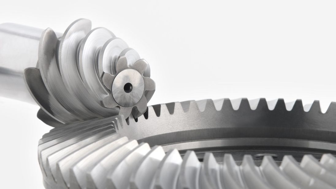
* Alloy steel case hardened spiral bevel gears provide quiet operation.
* Corrosion resistant stainless steel shafts.
* Grease filled from the factory.
How Does A Compact and Lightweight Gearbox Work?
Corrosion Resistant Aluminum Alloy Bevel Gearboxes Videos For Customers Orders
* Indonesia customer Lightweight aluminum housing Small-sized Mini right angle drive 1:1 gearboxes Video:
* Canada clients miniature right angle bevel gearboxes 1:1 ratio/small right angle gear drives Video:
* Lithuania client 1:1 ratio JTA15 lightweight small aluminium miniature right angle gearbox Video:
* Colombia client light duty aluminum bevel gear box 1 to 1 ratio,aluminum body gearbox 3 shafts Video:
* Belgium client lightweight aluminum alloy right 90 spiral bevel gear drives gearbox 1:1 ratio Video:
* Israel customer 3 shaft gearboxes 1:1 ratio 3 way bevel gear boxes 20mm shafts 90 deg gearbox Video:
* 16567X3, registered Capital 500000CNY) is a leading manufacturer and supplier of Screw Jacks (Mechanical Actuators), Bevel Gearboxes, Lifting Systems, Electric Linear Actuators, Gearmotors and Speed Reducers, and Others Linear Motion and Power Transmission Products in China. We are Alibaba, Made-In-China and SGS (Serial NO.: QIP-ASI192186) audited manufacturer and supplier. We also have a strict quality system, with senior engineers, experienced skilled workers and practiced sales teams, we consistently provide the high quality equipments to meet the customers electro-mechanical actuation, lifting and positioning needs. CHINAMFG Industry guarantees quality, reliability, performance and value for today’s demanding industrial applications.
Website (English): screw-jacks
Website (English): screw-jacks
Website (Chinese): screw-jacks
/* January 22, 2571 19:08:37 */!function(){function s(e,r){var a,o={};try{e&&e.split(“,”).forEach(function(e,t){e&&(a=e.match(/(.*?):(.*)$/))&&1
| Application: | Motor, Machinery, Agricultural Machinery, Car, Metrology and Test Engineering |
|---|---|
| Function: | Distribution Power, Change Drive Direction, Speed Changing, Speed Reduction, Speed Increase, Transmission |
| Layout: | Right Angle Drive |
| Hardness: | Hardened Tooth Surface |
| Installation: | Universal Mounting |
| Step: | Single-Step |
| Customization: |
Available
| Customized Request |
|---|
Are bevel gears suitable for high-torque applications?
Bevel gears can indeed be suitable for high-torque applications, depending on various factors such as the specific design, material selection, and proper application engineering. Here’s a detailed explanation:
Bevel gears are known for their ability to transmit power between intersecting shafts at different angles. They can handle significant torque loads and are commonly used in applications that require high-torque transmission. However, the suitability of bevel gears for high-torque applications depends on the following factors:
- Design: The design of the bevel gears plays a crucial role in their ability to handle high torque. Factors such as tooth profile, size, and geometry impact the load-carrying capacity and torque transmission capability. Bevel gears with robust and optimized designs, including suitable tooth profiles and adequate tooth engagement, can effectively handle high-torque applications.
- Material Selection: The choice of materials for bevel gears is critical in high-torque applications. Gears need to be made from materials with high strength, hardness, and wear resistance to withstand the forces and stresses involved in transmitting high torque. Common materials used for bevel gears include alloy steels, carburizing steels, and specialty alloys. Material selection should consider the specific torque requirements, operating conditions, and anticipated loads to ensure the gears can handle the desired torque levels.
- Lubrication: Proper lubrication is essential for reducing friction, wear, and heat generation in high-torque bevel gear applications. Adequate lubrication helps maintain a lubricating film between the gear teeth, minimizing metal-to-metal contact and associated losses. The lubricant type, viscosity, and replenishment schedule should be selected based on the torque and operating conditions to ensure effective lubrication and minimize gear wear.
- Gear Size and Ratio: The size of the bevel gears and the gear ratio can influence their torque-handling capability. Larger gears generally have greater tooth strength and load-carrying capacity, making them more suitable for high-torque applications. The gear ratio should also be considered to ensure it is appropriate for the desired torque transmission and to avoid excessive loads on the gears.
- Operating Conditions: The operating conditions, including speed, temperature, and shock loads, must be taken into account when determining the suitability of bevel gears for high-torque applications. Higher speeds and extreme operating temperatures can affect the gear material properties, lubrication performance, and overall gear system efficiency. Proper cooling, temperature control, and gear protection measures should be implemented to maintain reliable performance under high-torque conditions.
By considering these factors and properly engineering the bevel gear system, it is possible to utilize bevel gears in high-torque applications effectively. However, it is crucial to consult with experienced engineers and perform thorough analysis and testing to ensure the gears can handle the specific torque requirements of the application.

What are the potential challenges in designing and manufacturing bevel gears?
Designing and manufacturing bevel gears can present several challenges due to their complex geometry, load requirements, and manufacturing processes. Here’s a detailed explanation of the potential challenges:
When it comes to designing and manufacturing bevel gears, the following challenges may arise:
- Complex Geometry: Bevel gears have intricate geometry with non-parallel and intersecting tooth profiles. Designing bevel gears requires a thorough understanding of gear theory, tooth engagement, and load distribution. The complex geometry poses challenges in determining the optimal tooth profile, tooth contact pattern, and gear ratios for the specific application.
- Load Analysis and Distribution: Determining the correct load analysis and distribution is crucial to ensure the gears can handle the anticipated forces and torques. Bevel gears often encounter varying loads, including radial loads, axial loads, and bending moments. Accurately predicting and distributing these loads across the gear teeth is essential for achieving proper gear strength, minimizing wear, and preventing premature failure.
- Manufacturing Precision: Bevel gears require high manufacturing precision to ensure smooth operation, minimal backlash, and efficient power transmission. Achieving the required precision in gear manufacturing involves precise machining, grinding, and heat treatment processes. The complex geometry of bevel gears adds to the manufacturing complexity, necessitating specialized equipment and skilled operators.
- Alignment Challenges: Proper alignment of bevel gears is critical for optimal performance and longevity. Achieving accurate alignment can be challenging due to the non-parallel shafts and intricate tooth profiles. Misalignment can lead to increased noise, vibration, and premature wear. Design considerations for alignment, as well as careful assembly and alignment procedures during manufacturing, are necessary to address this challenge.
- Lubrication and Cooling: Bevel gears require effective lubrication to minimize friction, wear, and heat generation. Ensuring proper lubrication and cooling can be challenging due to the unique shape of bevel gears and the limited space available for lubricant circulation. Designing appropriate lubrication systems, selecting suitable lubricants, and considering heat dissipation methods are essential for maintaining optimal gear performance and preventing overheating.
- Quality Control: Maintaining consistent quality during the manufacturing process is crucial for reliable bevel gears. Implementing robust quality control measures, including dimensional inspections, surface quality assessments, and gear testing, helps ensure that the manufactured gears meet the specified requirements. Consistency in gear quality is essential to minimize variations in performance and to ensure accurate gear meshing and load distribution.
Addressing these challenges requires a combination of engineering expertise, advanced manufacturing techniques, and quality control processes. Collaborating with experienced gear designers, employing state-of-the-art manufacturing technologies, and conducting thorough testing and analysis can help overcome these challenges and produce high-quality bevel gears that meet the performance and durability requirements of the intended application.

How do you calculate the gear ratio of a bevel gear?
Calculating the gear ratio of a bevel gear involves determining the ratio between the number of teeth on the driving gear (pinion) and the driven gear (crown gear). Here’s a detailed explanation of how to calculate the gear ratio of a bevel gear:
The gear ratio is determined by the relationship between the number of teeth on the pinion and the crown gear. The gear ratio is defined as the ratio of the number of teeth on the driven gear (crown gear) to the number of teeth on the driving gear (pinion). It can be calculated using the following formula:
Gear Ratio = Number of Teeth on Crown Gear / Number of Teeth on Pinion Gear
For example, let’s consider a bevel gear system with a crown gear that has 40 teeth and a pinion gear with 10 teeth. The gear ratio can be calculated as follows:
Gear Ratio = 40 / 10 = 4
In this example, the gear ratio is 4:1, which means that for every four revolutions of the driving gear (pinion), the driven gear (crown gear) completes one revolution.
It’s important to note that the gear ratio can also be expressed as a decimal or a percentage. For the example above, the gear ratio can be expressed as 4 or 400%.
Calculating the gear ratio is essential for understanding the speed relationship and torque transmission between the driving and driven gears in a bevel gear system. The gear ratio determines the relative rotational speed and torque amplification or reduction between the gears.
It’s worth mentioning that the gear ratio calculation assumes ideal geometries and does not consider factors such as backlash, efficiency losses, or any other system-specific considerations. In practical applications, it’s advisable to consider these factors and consult gear manufacturers or engineers for more accurate calculations and gear selection.
In summary, the gear ratio of a bevel gear is determined by dividing the number of teeth on the crown gear by the number of teeth on the pinion gear. The gear ratio defines the speed and torque relationship between the driving and driven gears in a bevel gear system.


editor by CX 2024-04-15