Product Description
Genuine CZPT Tractor Parts 800.37.107 second hand shaft gear
|
Main parts |
Starter/ Alternator |
|
Rebuilt kit: Cylinder liner/ Piston/ Piston pin/ Piston ring/ circlip/ water seal O-ring |
|
|
Crankshaft/ thrust piece of crankshaft/ rock arm assembly |
|
|
Connecting rod/ Main Bearing shell/ Connecting rod Bearing |
|
|
Fuel injection pump/ Fuel injector/ Injector nozzle/ Plunger |
|
|
Cylinder head/ Head gasket/ cylinder block |
|
|
Intake valve/ exhaust valve |
|
|
Oil pump/Water pump assy/ injection pump |
|
|
Muffler& Filter/ Air filter/ Fuel filter/ Oil filter |
|
|
Flywheel/ flywheel box/ oil sump/ oil sump gasket/ fan |
We are supplier of full range Diesel engines spare parts.We stock more
than 10000+kinds of 100% Genuine spare parts at our warehouse.
Diesel engines brands and engines spare parts:
| Brands: | Models: | |||||||
| JIANGXIHU (WEST LAKE) DIS. | TY290 | TY295 | TY2110 | TY395 | JD490 | JD495 | JD4100 | JD4102 |
| XIHU (WEST LAKE) DIS.HU (WEST LAKE) DIS. | Y380 | Y385 | Y480 | Y485 | Y490 | Y4100 | Y4102 | Y4105 |
| XIHU (WEST LAKE) DIS.HU (WEST LAKE) DIS. | KM385TE | KM385BT | KM390BT | 4L22TE | 4L22TC | |||
| CHANGCHAI | EV80 | 3M78 | ZN385Q | ZN390T | ZN485Q | ZN490T | 4L68 | 4L88 |
| XINCHAI | A498BT | A498BZG | A490BPG | C490BPG | C490BT | 490BPG | 498BPG | |
| QUANCHAI | QC380 | QC385 | QC490 | QC495 | ||||
| YTO | YTR4105 | YTR4108 | ||||||
| LIJIA | SL2100 | SL2105 | SL3100 | SL3105ABT | SL4105ABT |
We can provide one-step service.
You can get perfect pre-sale and after-sales service from our company.
Just contact us please .
| Type: | Jinma Tractor Parts |
|---|---|
| Usage: | Jinma Tractor Spares |
| Material: | Iron |
| Power Source: | Diesel |
| Part Name: | Jinma Parts |
| Transport Package: | Carton |
| Customization: |
Available
| Customized Request |
|---|

Types of Miter Gears
The different types of miter gears include Hypoid, Crown, and Spiral. To learn more, read on. In addition, you’ll learn about their differences and similarities. This article will provide an overview of the different types of miter gears. You can also choose the type that fits your needs by using the guide below. After you’ve read it, you’ll know how to use them in your project. You’ll also learn how to pair them up by hand, which is particularly useful if you’re working on a mechanical component.
Bevel gears
Bevel and miter gears are both used to connect two shafts that have different axes. In most cases, these gears are used at right angles. The pitch cone of a bevel gear has the same shape as that of a spur gear, except the tooth profile is slightly tapered and has variable depth. The pinions of a bevel gear are normally straight, but can be curved or skew-shaped. They can also have an offset crown wheel with straight teeth relative to the axis.
In addition to their industrial applications, miter gears are found in agriculture, bottling, printing, and various industrial sectors. They are used in coal mining, oil exploration, and chemical processes. They are an important part of conveyors, elevators, kilns, and more. In fact, miter gears are often used in machine tools, like forklifts and jigsaws.
When considering which gear is right for a certain application, you’ll need to think about the application and the design goals. For example, you’ll want to know the maximum load that the gear can carry. You can use computer simulation programs to determine the exact torque required for a specific application. Miter gears are bevel gears that are geared on a single axis, not two.
To calculate the torque required for a particular application, you’ll need to know the MA of each bevel gear. Fortunately, you can now do so with CZPT. With the help of this software, you can generate 3D models of spiral bevel gears. Once you’ve created your model, you can then machine it. This can make your job much easier! And it’s fun!
In terms of manufacturing, straight bevel gears are the easiest to produce. The earliest method for this type of gear is a planer with an indexing head. Since the development of CNC machining, however, more effective manufacturing methods have been developed. These include CZPT, Revacycle, and Coniflex systems. The CZPT uses the Revacycle system. You can also use a CNC mill to manufacture spiral bevel gears.
Hypoid bevel gears
When it comes to designing hypoid bevel gears for miter and other kinds of gears, there are several important parameters to consider. In order to produce high-quality gearings, the mounting distance between the gear teeth and the pinion must be within a predefined tolerance range. In other words, the mounting distance between the gear teeth and pinion must be 0.05 mm or less.
To make this possible, the hypoid bevel gearset mesh is designed to involve sliding action. The result is a quiet transmission. It also means that higher speeds are possible without increasing noise levels. In comparison, bevel gears tend to be noisy at high speeds. For these reasons, the hypoid gearset is the most efficient way to build miter gears. However, it’s important to keep in mind that hypoid gears are not for every application.
Hypoid bevel gears are analogous to spiral bevels, but they don’t have intersecting axes. Because of this, they can produce larger pinions with smooth engagement. Crown bevel gears, on the other hand, have a 90-degree pitch and parallel teeth. Their geometry and pitch is unique, and they have particular geometrical properties. There are different ways to express pitch. The diametral pitch is the number of teeth, while circumferential measurement is called the circumference.
The face-milling method is another technique used for the manufacture of hypoid and spiral bevel gears. Face-milling allows gears to be ground for high accuracy and surface finish. It also allows for the elimination of heat treatment and facilitates the creation of predesigned ease-off topographies. Face-milling increases mechanical resistance by as much as 20%. It also reduces noise levels.
The ANSI/AGMA/ISO standards for geometric dimensioning differ from the best practices for manufacturing hypoid and bevel gears. The violation of common datum surfaces leads to a number of geometrical dimensioning issues. Moreover, hypoid gears need to be designed to incorporate the base pitches of the mating pinion and the hypoid bevel gear. This is not possible without knowing the base pitch of the gear and the mating pinion.
Crown bevel gears
When choosing crown bevels for a miter gear, you will need to consider a number of factors. Specifically, you will need to know the ratio of the tooth load to the bevel gear pitch radius. This will help you choose a bevel gear that possesses the right amount of excitation and load capacity. Crown bevels are also known as helical gears, which are a combination of two bevel gear types.
These bevel gears differ from spiral bevels because the bevels are not intersected. This gives you the flexibility of using a larger pinion and smoother engagement. Crown bevel gears are also named for their different tooth portions: the toe, or the part of the gear closest to the bore, and the heel, or the outermost diameter. The tooth height is smaller at the toe than it is at the heel, but the height of the gear is the same at both places.
Crown bevel gears are cylindrical, with teeth that are angled at an angle. They have a 1:1 gear ratio and are used for miter gears and spur gears. Crown bevel gears have a tooth profile that is the same as spur gears but is slightly narrower at the tip, giving them superior quietness. Crown bevel gears for miter gears can be made with an offset pinion.
There are many other options available when choosing a Crown bevel gear for miter gears. The material used for the gears can vary from plastics to pre-hardened alloys. If you are concerned with the material’s strength, you can choose a pre-hardened alloy with a 32-35 Rc hardness. This alloy also has the advantage of being more durable than plastic. In addition to being stronger, crown bevel gears are also easier to lubricate.
Crown bevel gears for miter gears are similar to spiral bevels. However, they have a hyperbolic, not conical, pitch surface. The pinion is often offset above or below the center of the gear, which allows for a larger diameter. Crown bevel gears for miter gears are typically larger than hypoid gears. The hypoid gear is commonly used in automobile rear axles. They are useful when the angle of rotation is 90 degrees. And they can be used for 1:1 ratios.
Spiral miter gears
Spiral bevel gears are produced by machining the face surface of the teeth. The process follows the Hertz theory of elastic contact, where the dislocations are equivalent to small significant dimensions of the contact area and the relative radii of curvature. This method assumes that the surfaces are parallel and that the strains are small. Moreover, it can reduce noise. This makes spiral bevel gears an ideal choice for high-speed applications.
The precision machining of CZPT spiral miter gears reduces backlash. They feature adjustable locking nuts that can precisely adjust the spacing between the gear teeth. The result is reduced backlash and maximum drive life. In addition, these gears are flexible enough to accommodate design changes late in the production process, reducing risk for OEMs and increasing efficiency and productivity. The advantages of spiral miter gears are outlined below.
Spiral bevel gears also have many advantages. The most obvious of these advantages is that they have large-diameter shafts. The larger shaft size allows for a larger diameter gear, but this means a larger gear housing. In turn, this reduces ground clearance, interior space, and weight. It also makes the drive axle gear larger, which reduces ground clearance and interior space. Spiral bevel gears are more efficient than spiral bevel gears, but it may be harder to find the right size for your application.
Another benefit of spiral miter gears is their small size. For the same amount of power, a spiral miter gear is smaller than a straight cut miter gear. Moreover, spiral bevel gears are less likely to bend or pit. They also have higher precision properties. They are suitable for secondary operations. Spiral miter gears are more durable than straight cut ones and can operate at higher speeds.
A key feature of spiral miter gears is their ability to resist wear and tear. Because they are constantly being deformed, they tend to crack in a way that increases their wear and tear. The result is a harder gear with a more contoured grain flow. But it is possible to restore the quality of your gear through proper maintenance. If you have a machine, it would be in your best interest to replace worn parts if they aren’t functioning as they should.


editor by CX 2023-04-22
China RV Hollow Shaft CM Type Motor Cycloidal Drive Pin Gear Speed Reducer with Flange spiral bevel gear
Applicable Industries: Garment Shops, Creating Content Retailers, Producing Plant, Machinery Fix Stores, Food & Beverage Manufacturing facility, Farms, Retail, Meals Store, Printing Retailers, Design works , Strength & Mining, Manufacturing facility Value Precision Miniature Travel Shaft and Worm Gear Packing Equipment, Printing, Conveyor, Laser Reducing
Gearing Arrangement: Cycloidal
Output Torque: Rated ninety eight ~ forty nine for ZF high positioning accuracy and smooth procedure. The composition of cycloidal pin gear pace reducer RV-CM series is made up of main bearing inner mechanism, double reduction gear, double column assistance mechanism, rolling contact system and pin gear system.The RV-CM sequence cycloidal equipment gearbox is an ideal velocity reducer for precision mechanical manage in the fields of equipment tools, factory robots, assembly products, conveying machines and other relevant fields which has the requirement for exact positioning, high rigidity and shock-load capacity. 1. Little vibration2. Substantial torsional rigidity3. Powerful influence resistance4. Superb starting up efficiency5. Dress in little, lengthy services life6. Lower backlash,significantly less than 1 arc. min.7. Dropped motion less than 1 arc. min. Interior main bearing.8. Major motor coupling Parts provided Thorough Pictures Specification Connected Merchandise Firm Introduction 3F Famed company designed from a manufacturing unit which professionally manufactures the gears. All staffs of manufacturing unit and R & D group have a lot more than twenty years’ CNC Machining Personalized Nylon Rack Modest Pinion Gears Plastic Ring Gear gear production and designing encounter. The manufacturing facility cooperated with planetary gearbox technologies crew in the early interval, and then recognized organization office of the planetary gearbox, and produced the layout and producing process of product line of planetary gearbox collection. Items can be suitable with servo motors and stepper motors created by any servo manufacturing unit. Substantial precision planetary reducers features of lowering rotating speed, increasing torque significantly, rising inertia of the motor rotor, enhancing rigidity, shortening the finding time of commence and end, miniaturizing the motor energy and bettering the steadiness of the inertia load and decreasing the vibration at the same time. Our Providers & Power one. Affordable options of German Alpha, Neugart, Japan Shimpo, China Prolonged daily life higher performance K collection strength preserving helical-bevel modular gear velocity reducer inline gearbox prices Harmonic Drive, ZheJiang Apex, and so forth.2. Shipping and delivery time could be negotiated if you are urgent.3. OEM support is suitable.4. Thorough after-product sales provider and cost-free complex assistance.5. High top quality at affordable rates.
Types of Miter Gears
The different types of miter gears include Hypoid, Crown, and Spiral. To learn more, read on. In addition, you’ll learn about their differences and similarities. This article will provide an overview of the different types of miter gears. You can also choose the type that fits your needs by using the guide below. After you’ve read it, you’ll know how to use them in your project. You’ll also learn how to pair them up by hand, which is particularly useful if you’re working on a mechanical component.
Bevel gears
Bevel and miter gears are both used to connect two shafts that have different axes. In most cases, these gears are used at right angles. The pitch cone of a bevel gear has the same shape as that of a spur gear, except the tooth profile is slightly tapered and has variable depth. The pinions of a bevel gear are normally straight, but can be curved or skew-shaped. They can also have an offset crown wheel with straight teeth relative to the axis.
In addition to their industrial applications, miter gears are found in agriculture, bottling, printing, and various industrial sectors. They are used in coal mining, oil exploration, and chemical processes. They are an important part of conveyors, elevators, kilns, and more. In fact, miter gears are often used in machine tools, like forklifts and jigsaws.
When considering which gear is right for a certain application, you’ll need to think about the application and the design goals. For example, you’ll want to know the maximum load that the gear can carry. You can use computer simulation programs to determine the exact torque required for a specific application. Miter gears are bevel gears that are geared on a single axis, not two.
To calculate the torque required for a particular application, you’ll need to know the MA of each bevel gear. Fortunately, you can now do so with CZPT. With the help of this software, you can generate 3D models of spiral bevel gears. Once you’ve created your model, you can then machine it. This can make your job much easier! And it’s fun!
In terms of manufacturing, straight bevel gears are the easiest to produce. The earliest method for this type of gear is a planer with an indexing head. Since the development of CNC machining, however, more effective manufacturing methods have been developed. These include CZPT, Revacycle, and Coniflex systems. The CZPT uses the Revacycle system. You can also use a CNC mill to manufacture spiral bevel gears.
Hypoid bevel gears
When it comes to designing hypoid bevel gears for miter and other kinds of gears, there are several important parameters to consider. In order to produce high-quality gearings, the mounting distance between the gear teeth and the pinion must be within a predefined tolerance range. In other words, the mounting distance between the gear teeth and pinion must be 0.05 mm or less.
To make this possible, the hypoid bevel gearset mesh is designed to involve sliding action. The result is a quiet transmission. It also means that higher speeds are possible without increasing noise levels. In comparison, bevel gears tend to be noisy at high speeds. For these reasons, the hypoid gearset is the most efficient way to build miter gears. However, it’s important to keep in mind that hypoid gears are not for every application.
Hypoid bevel gears are analogous to spiral bevels, but they don’t have intersecting axes. Because of this, they can produce larger pinions with smooth engagement. Crown bevel gears, on the other hand, have a 90-degree pitch and parallel teeth. Their geometry and pitch is unique, and they have particular geometrical properties. There are different ways to express pitch. The diametral pitch is the number of teeth, while circumferential measurement is called the circumference.
The face-milling method is another technique used for the manufacture of hypoid and spiral bevel gears. Face-milling allows gears to be ground for high accuracy and surface finish. It also allows for the elimination of heat treatment and facilitates the creation of predesigned ease-off topographies. Face-milling increases mechanical resistance by as much as 20%. It also reduces noise levels.
The ANSI/AGMA/ISO standards for geometric dimensioning differ from the best practices for manufacturing hypoid and bevel gears. The violation of common datum surfaces leads to a number of geometrical dimensioning issues. Moreover, hypoid gears need to be designed to incorporate the base pitches of the mating pinion and the hypoid bevel gear. This is not possible without knowing the base pitch of the gear and the mating pinion.
Crown bevel gears
When choosing crown bevels for a miter gear, you will need to consider a number of factors. Specifically, you will need to know the ratio of the tooth load to the bevel gear pitch radius. This will help you choose a bevel gear that possesses the right amount of excitation and load capacity. Crown bevels are also known as helical gears, which are a combination of two bevel gear types.
These bevel gears differ from spiral bevels because the bevels are not intersected. This gives you the flexibility of using a larger pinion and smoother engagement. Crown bevel gears are also named for their different tooth portions: the toe, or the part of the gear closest to the bore, and the heel, or the outermost diameter. The tooth height is smaller at the toe than it is at the heel, but the height of the gear is the same at both places.
Crown bevel gears are cylindrical, with teeth that are angled at an angle. They have a 1:1 gear ratio and are used for miter gears and spur gears. Crown bevel gears have a tooth profile that is the same as spur gears but is slightly narrower at the tip, giving them superior quietness. Crown bevel gears for miter gears can be made with an offset pinion.
There are many other options available when choosing a Crown bevel gear for miter gears. The material used for the gears can vary from plastics to pre-hardened alloys. If you are concerned with the material’s strength, you can choose a pre-hardened alloy with a 32-35 Rc hardness. This alloy also has the advantage of being more durable than plastic. In addition to being stronger, crown bevel gears are also easier to lubricate.
Crown bevel gears for miter gears are similar to spiral bevels. However, they have a hyperbolic, not conical, pitch surface. The pinion is often offset above or below the center of the gear, which allows for a larger diameter. Crown bevel gears for miter gears are typically larger than hypoid gears. The hypoid gear is commonly used in automobile rear axles. They are useful when the angle of rotation is 90 degrees. And they can be used for 1:1 ratios.
Spiral miter gears
Spiral bevel gears are produced by machining the face surface of the teeth. The process follows the Hertz theory of elastic contact, where the dislocations are equivalent to small significant dimensions of the contact area and the relative radii of curvature. This method assumes that the surfaces are parallel and that the strains are small. Moreover, it can reduce noise. This makes spiral bevel gears an ideal choice for high-speed applications.
The precision machining of CZPT spiral miter gears reduces backlash. They feature adjustable locking nuts that can precisely adjust the spacing between the gear teeth. The result is reduced backlash and maximum drive life. In addition, these gears are flexible enough to accommodate design changes late in the production process, reducing risk for OEMs and increasing efficiency and productivity. The advantages of spiral miter gears are outlined below.
Spiral bevel gears also have many advantages. The most obvious of these advantages is that they have large-diameter shafts. The larger shaft size allows for a larger diameter gear, but this means a larger gear housing. In turn, this reduces ground clearance, interior space, and weight. It also makes the drive axle gear larger, which reduces ground clearance and interior space. Spiral bevel gears are more efficient than spiral bevel gears, but it may be harder to find the right size for your application.
Another benefit of spiral miter gears is their small size. For the same amount of power, a spiral miter gear is smaller than a straight cut miter gear. Moreover, spiral bevel gears are less likely to bend or pit. They also have higher precision properties. They are suitable for secondary operations. Spiral miter gears are more durable than straight cut ones and can operate at higher speeds.
A key feature of spiral miter gears is their ability to resist wear and tear. Because they are constantly being deformed, they tend to crack in a way that increases their wear and tear. The result is a harder gear with a more contoured grain flow. But it is possible to restore the quality of your gear through proper maintenance. If you have a machine, it would be in your best interest to replace worn parts if they aren’t functioning as they should.
editor by czh 2023-03-04
China 0.12kw-200kw F Series Parallel Hollow Shaft Helical Speed Reducing Gear Motor for Belt Conveyor helical bevel gear
Merchandise Description
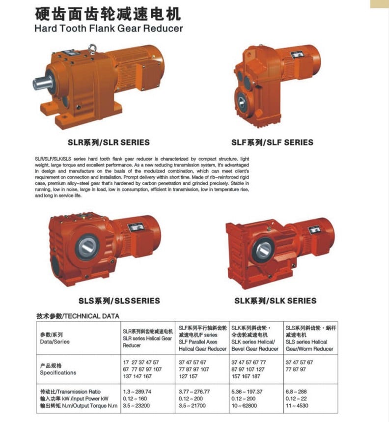
F Sequence Parallel Shaft Helical Geared Motor
| Data/Series | Product |
| Specs | 127 157 |
| Ratio | 3.seventy seven~276.77 |
| Enter Electricity(Kw) | 0.twelve~two hundred |
| Output Torque(N.m) | 3.5~21700 |
| Type | Product | Ratio | Input Electrical power (KW) | Nominal Torque(N.m) | Input Velocity (Rpm) |
| GF sequence Parallel Shaft Helical Geared Motor | F37 | 3.eighty one-128.fifty one | .eighteen-three | two hundred |
750Rpm |
| F47 | 5.08-189.39 | .eighteen-three | four hundred | ||
| F57 | five.eighteen-199.70 | .18-5.five | 600 | ||
| F67 | four.21-228.ninety nine | .18-5.five | 820 | ||
| F77 | four.thirty-281.71 | .37-11 | 1550 | ||
| F87 | four.twelve-270.sixty eight | .75-22 | 2700 | ||
| F97 | four.68-280.seventy six | one.1-thirty | 4300 | ||
| F107 | 6.twenty-254.forty | 2.2-forty five | 7840 | ||
| F127 | 4.63-172.seventeen | seven.5-90 | 13000 | ||
| F157 | 11.92-267.43 | eleven-200 | 18000 |
Un-standard merchandise or OEM is hugely welcome, and gearbox components could be also offered to you.
Application fields
metal, chemical, oil, consume, foodstuff, electronic, method hides, pharmacy, and textile.
They are commonly utilized in various reduced-velocity transmissions, which are basic basic parts of mechanical transmission.
Attributes of Items
1,very normal modular developed according to global common
2,high precision, large performance, fantastic classification in transmission ratio
three,vast range, huge transmission torque,
4,reputable functionality, low noise,
5,adaptable set up, and convenient use and maintenance.
FAQ
Q: What is your MOQ of this merchandise?
A: 10PCS.
For the initial time cooperation, we acknowledge demo sample buy.
Q: What’s your payment terms?
A: 30% T/T deposit, 70% balance prior to cargo or L/C at sight.
Q: What is the shipping and delivery time?
A: 20-30 days following obtaining your L/C or T/T deposit.
Q: Can we used our personal brand name on motors ?
A: Certain, we can offer OEM service, manufacture with your licensed manufacturer.
Q: How long is your warranty?
A: 12 months after getting B/L.
Manufacturing facility
Our Office Block
Firm Staff
|
US $100-4,000 / Piece | |
1 Piece (Min. Order) |
###
| Application: | Industry |
|---|---|
| Hardness: | Hardened Tooth Surface |
| Installation: | Vertical Type |
| Layout: | Coaxial |
| Gear Shape: | Bevel Gear |
| Step: | Single-Step |
###
| Customization: |
Available
|
|---|
###
| Data/Series | Model |
| Specifications | 37 47 57 67 77 87 97 107 127 157 |
| Ratio | 3.77~276.77 |
| Input Power(Kw) | 0.12~200 |
| Output Torque(N.m) | 3.5~21700 |
###
| Type | Model | Ratio | Input Power (KW) | Nominal Torque(N.m) | Input Speed (Rpm) |
| GF series Parallel Shaft Helical Geared Motor | F37 | 3.81-128.51 | 0.18-3 | 200 |
750Rpm |
| F47 | 5.08-189.39 | 0.18-3 | 400 | ||
| F57 | 5.18-199.70 | 0.18-5.5 | 600 | ||
| F67 | 4.21-228.99 | 0.18-5.5 | 820 | ||
| F77 | 4.30-281.71 | 0.37-11 | 1550 | ||
| F87 | 4.12-270.68 | 0.75-22 | 2700 | ||
| F97 | 4.68-280.76 | 1.1-30 | 4300 | ||
| F107 | 6.20-254.40 | 2.2-45 | 7840 | ||
| F127 | 4.63-172.17 | 7.5-90 | 13000 | ||
| F157 | 11.92-267.43 | 11-200 | 18000 |
|
US $100-4,000 / Piece | |
1 Piece (Min. Order) |
###
| Application: | Industry |
|---|---|
| Hardness: | Hardened Tooth Surface |
| Installation: | Vertical Type |
| Layout: | Coaxial |
| Gear Shape: | Bevel Gear |
| Step: | Single-Step |
###
| Customization: |
Available
|
|---|
###
| Data/Series | Model |
| Specifications | 37 47 57 67 77 87 97 107 127 157 |
| Ratio | 3.77~276.77 |
| Input Power(Kw) | 0.12~200 |
| Output Torque(N.m) | 3.5~21700 |
###
| Type | Model | Ratio | Input Power (KW) | Nominal Torque(N.m) | Input Speed (Rpm) |
| GF series Parallel Shaft Helical Geared Motor | F37 | 3.81-128.51 | 0.18-3 | 200 |
750Rpm |
| F47 | 5.08-189.39 | 0.18-3 | 400 | ||
| F57 | 5.18-199.70 | 0.18-5.5 | 600 | ||
| F67 | 4.21-228.99 | 0.18-5.5 | 820 | ||
| F77 | 4.30-281.71 | 0.37-11 | 1550 | ||
| F87 | 4.12-270.68 | 0.75-22 | 2700 | ||
| F97 | 4.68-280.76 | 1.1-30 | 4300 | ||
| F107 | 6.20-254.40 | 2.2-45 | 7840 | ||
| F127 | 4.63-172.17 | 7.5-90 | 13000 | ||
| F157 | 11.92-267.43 | 11-200 | 18000 |
Types of Bevel Gears
Bevel Gears are used in a number of industries. They are used in wheeled excavators, dredges, conveyor belts, mill actuators, and rail transmissions. A bevel gear’s spiral or angled bevel can make it suitable for confined spaces. It is also used in robotics and vertical supports of rolling mills. You can use bevel gears in food processing processes. For more information on bevel gears, read on.
Spiral bevel gear
Spiral bevel gears are used to transmit power between two shafts in a 90-degree orientation. They have curved or oblique teeth and can be fabricated from various metals. Bestagear is one manufacturer specializing in medium to large spiral bevel gears. They are used in the mining, metallurgical, marine, and oil fields. Spiral bevel gears are usually made from steel, aluminum, or phenolic materials.
Spiral bevel gears have many advantages. Their mesh teeth create a less abrupt force transfer. They are incredibly durable and are designed to last a long time. They are also less expensive than other right-angle gears. They also tend to last longer, because they are manufactured in pairs. The spiral bevel gear also reduces noise and vibration from its counterparts. Therefore, if you are in need of a new gear set, spiral bevel gears are the right choice.
The contact between spiral bevel gear teeth occurs along the surface of the gear tooth. The contact follows the Hertz theory of elastic contact. This principle holds for small significant dimensions of the contact area and small relative radii of curvature of the surfaces. In this case, strains and friction are negligible. A spiral bevel gear is a common example of an inverted helical gear. This gear is commonly used in mining equipment.
Spiral bevel gears also have a backlash-absorbing feature. This feature helps secure the thickness of the oil film on the gear surface. The shaft axis, mounting distance, and angle errors all affect the tooth contact on a spiral bevel gear. Adjusting backlash helps to correct these problems. The tolerances shown above are common for bevel gears. In some cases, manufacturers make slight design changes late in the production process, which minimizes the risk to OEMs.
Straight bevel gear
Straight bevel gears are among the easiest types of gears to manufacture. The earliest method used to manufacture straight bevel gears was to use a planer equipped with an indexing head. However, improvements have been made in manufacturing methods after the introduction of the Revacycle system and the Coniflex. The latest technology allows for even more precise manufacturing. Both of these manufacturing methods are used by CZPT. Here are some examples of straight bevel gear manufacturing.
A straight bevel gear is manufactured using two kinds of bevel surfaces, namely, the Gleason method and the Klingelnberg method. Among the two, the Gleason method is the most common. Unlike other types of gear, the CZPT method is not a universal standard. The Gleason system has higher quality gears, since its adoption of tooth crowning is the most effective way to make gears that tolerate even small assembly errors. It also eliminates the stress concentration in the bevelled edges of the teeth.
The gear’s composition depends on the application. When durability is required, a gear is made of cast iron. The pinion is usually three times harder than the gear, which helps balance wear. Other materials, such as carbon steel, are cheaper, but are less resistant to corrosion. Inertia is another critical factor to consider, since heavier gears are more difficult to reverse and stop. Precision requirements may include the gear pitch and diameter, as well as the pressure angle.
Involute geometry of a straight bevel gear is often computed by varying the surface’s normal to the surface. Involute geometry is computed by incorporating the surface coordinates and the theoretical tooth thickness. Using the CMM, the spherical involute surface can be used to determine tooth contact patterns. This method is useful when a roll tester tooling is unavailable, because it can predict the teeth’ contact pattern.
Hypoid bevel gear
Hypoid bevel gears are an efficient and versatile speed reduction solution. Their compact size, high efficiency, low noise and heat generation, and long life make them a popular choice in the power transmission and motion control industries. The following are some of the benefits of hypoid gearing and why you should use it. Listed below are some of the key misperceptions and false assumptions of this gear type. These assumptions may seem counterintuitive at first, but will help you understand what this gear is all about.
The basic concept of hypoid gears is that they use two non-intersecting shafts. The smaller gear shaft is offset from the larger gear shaft, allowing them to mesh without interference and support each other securely. The resulting torque transfer is improved when compared to conventional gear sets. A hypoid bevel gear is used to drive the rear axle of an automobile. It increases the flexibility of machine design and allows the axes to be freely adjusted.
In the first case, the mesh of the two bodies is obtained by fitting the hyperboloidal cutter to the desired gear. Its geometric properties, orientation, and position determine the desired gear. The latter is used if the desired gear is noise-free or is required to reduce vibrations. A hyperboloidal cutter, on the other hand, meshes with two toothed bodies. It is the most efficient option for modeling hypoid gears with noise concerns.
The main difference between hypoid and spiral bevel gears is that the hypoid bevel gear has a larger diameter than its counterparts. They are usually found in 1:1 and 2:1 applications, but some manufacturers also provide higher ratios. A hypoid gearbox can achieve speeds of three thousand rpm. This makes it the preferred choice in a variety of applications. So, if you’re looking for a gearbox with a high efficiency, this is the gear for you.
Addendum and dedendum angles
The addendum and dedendum angles of a bevel gear are used to describe the shape and depth of the teeth of the gear. Each tooth of the gear has a slightly tapered surface that changes in depth. These angles are defined by their addendum and dedendum distances. Addendum angle is the distance between the top land and the bottom surface of the teeth, while dedendum angle is the distance between the pitch surface and the bottom surface of the teeth.
The pitch angle is the angle formed by the apex point of the gear’s pitch cone with the pitch line of the gear shaft. The dedendum angle, on the other hand, is the depth of the tooth space below the pitch line. Both angles are used to measure the shape of a bevel gear. The addendum and dedendum angles are important for gear design.
The dedendum and addendum angles of a bevel gear are determined by the base contact ratio (Mc) of the two gears. The involute curve is not allowed to extend within the base diameter of the bevel gear. The base diameter is also a critical measurement for the design of a gear. It is possible to reduce the involute curve to match the involute curve, but it must be tangential to the involute curve.
The most common application of a bevel gear is the automotive differential. They are used in many types of vehicles, including cars, trucks, and even construction equipment. They are also used in the marine industry and aviation. Aside from these two common uses, there are many other uses for bevel gears. And they are still growing in popularity. But they’re a valuable part of automotive and industrial gearing systems.
Applications of bevel gears
Bevel gears are used in a variety of applications. They are made of various materials depending on their weight, load, and application. For high-load applications, ferrous metals such as grey cast iron are used. These materials have excellent wear resistance and are inexpensive. For lower-weight applications, steel or non-metals such as plastics are used. Some bevel gear materials are considered noiseless. Here are some of their most common uses.
Straight bevel gears are the easiest to manufacture. The earliest method of manufacturing them was with a planer with an indexing head. Modern manufacturing methods introduced the Revacycle and Coniflex systems. For industrial gear manufacturing, the CZPT uses the Revacycle system. However, there are many types of bevel gears. This guide will help you choose the right material for your next project. These materials can withstand high rotational speeds and are very strong.
Bevel gears are most common in automotive and industrial machinery. They connect the driveshaft to the wheels. Some even have a 45-degree bevel. These gears can be placed on a bevel surface and be tested for their transmission capabilities. They are also used in testing applications to ensure proper motion transmission. They can reduce the speed of straight shafts. Bevel gears can be used in many industries, from marine to aviation.
The simplest type of bevel gear is the miter gear, which has a 1:1 ratio. It is used to change the axis of rotation. The shafts of angular miter bevel gears can intersect at any angle, from 45 degrees to 120 degrees. The teeth on the bevel gear can be straight, spiral, or Zerol. And as with the rack and pinion gears, there are different types of bevel gears.
editor by czh 2022-12-13
Best China manufacturer & factory F series parallel shaft gearbox helical worm gear speed reducer electric motor for concrete mixer With high quality best price

If you are interested in any of our products or would like to discuss a potential order, please feel free to contact us.
Overview
Quick Details
- Applicable Industries:
-
Hotels, Garment Shops, Building Material Shops, Manufacturing Plant, Machinery Repair Shops, Food & Beverage Factory, farms, Energy & Mining, Construction works
- Place of Origin:Zhejiang, China
- Brand Name:
-
OEM
- Gearing Arrangement:
-
Helical
- Output Torque:
-
3.5~21700N.m
- Input Speed:
-
1450/960rpm
- The result is a drive solution that reflects our bundled practical knowledge, which is perfectly adapted to your requirements as a customer. However, our task does not end with delivery and installation. We are always there to provide you with advice and assistance throughout the entire lifecycle of our products. Output Speed:
-
14-280rpm
- Ratio:
-
3.77~276.77
- Certification:
-
ISO9001-2008
- Mount Position:
-
Foot Mounted
- Bearing:
-
LYC, HRB,ZWZ,NSK
- Warranty:
-
1 Year
- Color:
-
Blue
Supply Ability
- Supply Ability:
- 500 Unit/Units per Month
Packaging & Delivery
- Packaging Details
- Wooden boxes , Cantons packed in 1 pallet
- Port
- Ningbo Port, Shanghai Port
Online Customization
F series parallel shaft gearbox helical worm gear speed reducer electric motor for concrete mixer
Product Description
F series gear reducer is one kind of parallel shaft helical gear reducer , which consist of 2 or 3 stages helical gears (relate to gear ratio) in the same case . The hard tooth surface gear use the high quality alloy steel ,the process of carburizing and quenching, grinding ,which give it follow Main products include: manure spreading truck, potato planting/harvesting machine, disc plough, disc harrow, grass Mower/slasher, corn and wheat thershers, seeder, mouldboard plow, deep subsoiler machines, rotary tiller, rear blade, fertilizer spreader, combine rice harvester, corn thresher, farm trailer, ridger, trencher, stubble cleaner, earth auger, cultivator and its accessories: Plow disc blades, harrowing film, plough tip and share, cultivator tine, casting parts etc.characters :Stable transmission ,low noise and temperature ,high loading ,long working lift . Wide application ,specialize in Metallurgy ,Sewage treatment,
Chemical Industry , Pharmacy ,Agriculture equipment and Oil industry.
Specifications:
1) Output speed: 0.6~1,028r/min
2) Output torque: up to 21700N.m
3) Motor power: 0.12~200kW
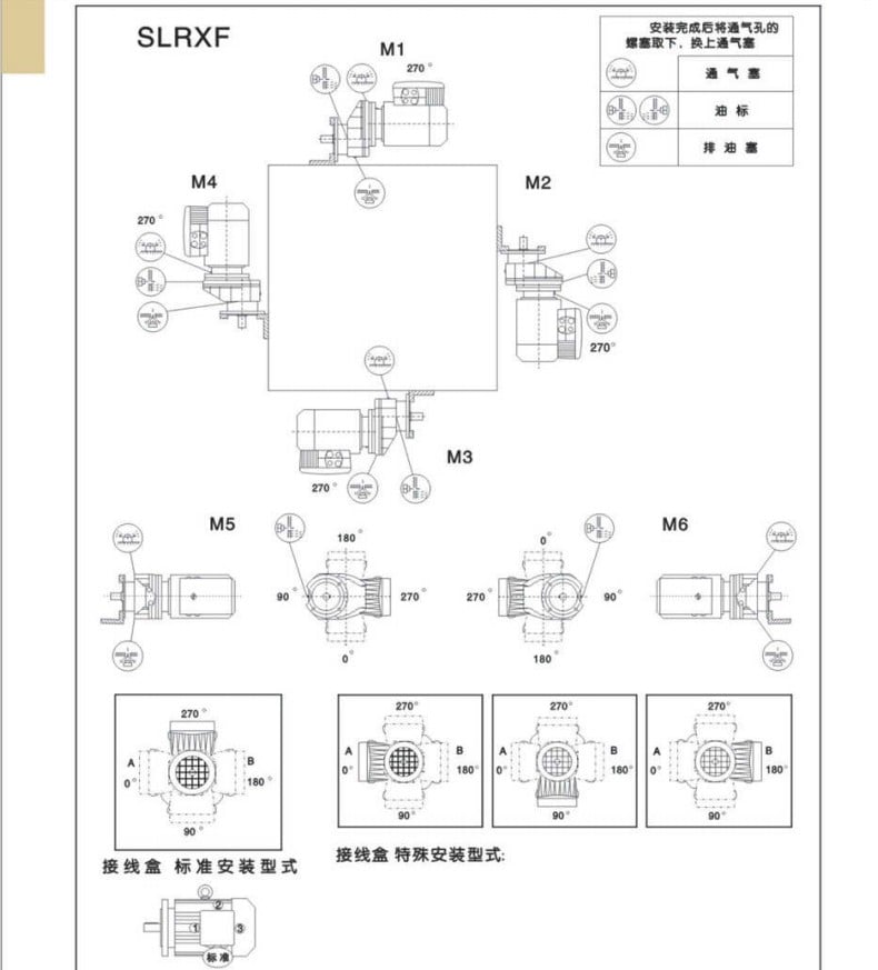
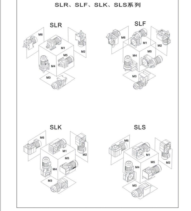
4) Mounted form: foot-mounted and flange-mounted mounting
|
Product Name |
SLK Series Rigid Tooth helical bevel reducer |
|
Gear Material |
20CrMnTi |
|
Case Material |
HT250 |
|
Shaft Material |
20CrMnTi |
|
Gear Processing |
Grinding finish by HOFLER Grinding Machines |
|
Color |
Customized |
|
Noise Test |
65~70dB |
|
Efficiency |
94%~98% (depends on the transmission stage) |
|
Lubricating oil |
Shell Omala synthetic oil or mineral oil , or similar brand |
|
Heat treatment |
tempering, cementiting, quenching,etc. |
|
Brand of bearings |
C&U bearing, ZWZ,LYC, HRB, SKF,NSK and so on |
|
Brand of oil seal |
NAK or other brand |
|
Temp. rise (MAX) |
40 ° |
|
Temp. rise (Oil)(MAX) |
50 ° |
|
Vibration |
≤20µm |
Company Information
Certifications

Our Services
Packaging & Shipping

Expo& CuPTO shaft connectors on tractors are not standardized which can lead to complications when connecting the PTO shaft. For example, some older tractor models have the connection flange closer to the tractor itself making it difficult to connect and lead to a potential safety hazard.stomers
FAQ
: Are you trading company or manufacturer ?
A: We are factory.
Q: How long is your delivery time?
A: Generally it is 5-10 days if the goods are in stock. or it is 15-20 days if the goods are not in stock, it is according to quantity.
Q: Do you provide samples ? is it free or extra ?
A: Yes, we could offer the sample for free charge but do not pay the cost of freight.
Q: What is your terms of payment ?
A: Payment=1000USD, 30% T/T in advance ,balance before shippment.
If you have another question, pls feel free to contact us as below:
Contact us


china High Quality Price Ratio supplier hydraulic gear motorsmall hollow shaft hydraulic motorhollow shaft hydraulic motor

our items are selling well in the American, European, South American and Asian marketplaces. a specialized provider of a full assortment of chains, sprockets, gears, gear racks, V-belts, couplings and reducers, pto shaft, agricultural gearboxes….
Overview
Fast Information
- After Guarantee Services:
-
Video clip technical assistance
- Nearby Support Location:
-
Egypt
- Showroom Area:
-
Egypt
- Kind:
-
components
- Soon after-income Support Provided:
-
Video clip specialized assist
Supply Ability
- Provide Ability:
- 3000 Piece/Pieces per Month
Packaging & Supply
- Packaging Particulars
- Carton or Plywood case or PALLET
On-line Customization
scorching china merchandise wholesale hollow shaft hydraulic motor
Merchandise Description
Specifications
Orbit hydraulic motor
Interchangable with Char-lynn H and S collection.
forty a long time manufacturing activities
Export to wolrd market place
one. This series of motor, with its shell manufactured of ductile solid iron of adequate depth, can be used to circumstances with considerably less load and interval operation, broadly to agriculture, forestry, plastics, equipment resources and minmachines, such as the mould top adjustment of the injection molding device, the cleaner, the saw, the worktable and so forth.
2. The output shaft, with the deep groove ball bearing, can bear certain axial power and radial pressure.
three. With the axial oil distribution structur, it is of smaller dimensions and considerably less fat.
four. With two interior verify valves, no drain link.
5. With cycoid group with the roller, it has a modest friction and hygh mechanical performance.
6. BMR sequence is equal to Charlynn “H” and “S” kind, and also can substitute for White, Parker, Eaton.
Technical Information
| Variety | BMR-fifty | BMR-eighty | BMR-a hundred | BMR-a hundred twenty five | BMR-one hundred sixty | BMR-200 | BMR-250 | BMR-315 | BMR-four hundred | |
| Displacement(ml/r) | fifty one.7 | eighty.5 | 100.5 | 126.3 | a hundred and sixty.eight | 200.nine | 252.6 | 321.five | 401.nine | |
| Max.Force.Fall(Mpa) | cont. | fourteen | fourteen | 14 | fourteen | fourteen | fourteen | 11 | nine | 7 |
| int. | seventeen.five | 17.5 | 17.5 | 17.five | seventeen.five | seventeen.five | fourteen | eleven | 9 | |
| peak. | twenty | 20 | 20 | twenty | twenty | twenty | 16 | thirteen | eleven | |
| Max.torque(N.m) | cont. | ninety three | 152 | 194 | 237 | 310 | 369 | 380 | 380 | 380 |
| int. | 118 | 189 | 236 | 296 | 378 | 450 | 470 | 470 | 470 | |
| peak. | one hundred thirty five | 216 | 270 | 338 | 433 | 509 | 540 | 540 | 540 | |
| Speed.Assortment(cont.)(r/min) | 10-775 | 10-750 | 10-600 | 9-475 | 7-375 | 5-300 | 5-240 | five-one hundred ninety | five-a hundred and sixty | |
| Max.Flow(cont.)(L/min) | 40 | 60 | 60 | 60 | 60 | sixty | sixty | 60 | sixty | |
| Max.Output.Energy(cont.)(Kw) | 7 | 10 | ten | 10 | 10 | eight | 6 | five | four | |
| Fat(kg) | 6.5 | six.9 | 7 | seven.3 | 7.five | 8 | eight.five | nine | eleven | |
Far more Products
Packaging & Shipping and delivery
Company Information
FAQ
Our Solutions
Speak to US